Chapter 3 Installation Drawing 35
LIEBERT APM UPS Module And Parallel System 30kVA~150kVA User Manual
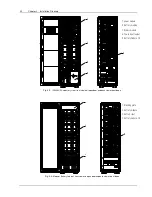
SCR
Rectifier fan
Main power board M4
Bypass DSP board U3
Intellislots
Monitoring transfer
board X1
Auxiliary power board M3
Dry contact and parallel
signal board X2
Fig.
4-14
: Static Bypass Module
Notes for installing bypass power modules:
1. When installing the modules, install the modules from bottom to top. When removing the modules, remove the
modules from top to bottom. The purpose is to maintain the stable center of gravity.
2. When inserting the module, ensure that the “Ready” switch is in unready status.
3. After inserting the module, tighten all the screws before closing the ready switch.
4. When removing the modules, turn off the ready switch first, remove the screws and then remove the modules.
5. Wait for 5 minutes before inserting the removed modules.
4.1 Internal Battery Module
4.1.1 Appearance Of Internal Battery Module
1.
Battery Box
2.
Battery Boxes Terminals
3
.
Battery Module Terminals
4.
Circuit Breaker
5.
Battery Tray
Summary of Contents for Liebert APM
Page 4: ......

