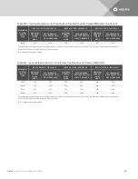
Select the appropriate input cables according to Table 3.2 below and Table 3.3 below based on the UPS
rating and mains frequency; however, it is recommended that you size the over current protection and
wiring for the frame rating to easily allow upgrades to the UPS system.
MAXIMUM
SYSTEM
RATED LOAD
INPUT VOLTAGE - 200VAC
INPUT VOLTAGE - 208VAC
INPUT VOLTAGE - 240VAC
MAXIMUM
CURRENT
IN UPS
MODE
RECOMMENDED
INPUT
PROTECTION
CIRCUIT BREAKER
MAXIMUM
CURRENT
IN UPS
MODE
RECOMMENDED
INPUT
PROTECTION
CIRCUIT BREAKER
MAXIMUM
CURRENT
IN UPS
MODE
RECOMMENDED
INPUT
PROTECTION
CIRCUIT BREAKER
5kVA
27A
50A
26A
50A
23A
50A
10kVA
53A
63A
51A
63A
45A
63A
15kVA
80A
100A
77A
100A
67A
100A
20kVA
106A
125A
102A
125A
90A
125A
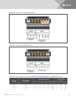
The power input and output terminals accept a maximum cable cross-sectional area of 35 mm
2
(2 AWG); the minimum cable cross-sectional area is
16 mm
2
(6 AWG); the rated torque is 4.52 Nm (40 in-lb).
Use of 90°C copper wire is recommended
Table 3.2 Input cable selection list—60Hz
MAXIMUM
SYSTEM
RATED
LOAD
INPUT VOLTAGE - 220VAC
INPUT VOLTAGE - 230VAC
INPUT VOLTAGE - 240VAC
MAXIMUM
CURRENT
IN UPS
MODE
RECOMMENDED
INPUT PROTECTION
CIRCUIT BREAKER
MAXIMUM
CURRENT
IN UPS
MODE
RECOMMENDED
INPUT PROTECTION
CIRCUIT BREAKER
MAXIMUM
CURRENT
IN UPS
MODE
RECOMMENDED
INPUT PROTECTION
CIRCUIT BREAKER
5kVA
25A
50A
24A
50A
23A
50A
10kVA
49A
63A
47A
63A
45A
63A
15kVA
73A
100A
70A
100A
67A
100A
20kVA
97A
125A
93A
125A
90A
125A
The power input and output terminals accept a maximum cable cross-sectional area of 35 mm
2
(2 AWG); the minimum cable cross-sectional area is
16 mm
2
(6 AWG); the rated torque is 4.52 Nm (40 in-lb).
90°C copper wire recommended
Table 3.3 Input cable selection list—50Hz
To connect the cable:
NOTE: Input and output cables must be run in separate conduit before cable connection. If your input
power grid is L-L line voltage, the input N of the power input and output terminals will connect live wire,
so the output N of the power input and output terminals is also live wire.
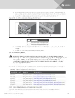
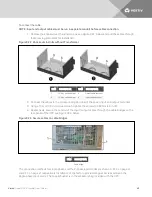
1. Remove the knockouts at the junction box, see Figure 3.13 on the next page, and pull the
cables through them, leaving some slack for installation.
Vertiv
| Liebert® APS™ Installer/User Guide |
33
Summary of Contents for Liebert APS series
Page 1: ...Liebert APS 5 20 kVA Modular UPS Installer User Guide...
Page 6: ...Vertiv Liebert APS Installer User Guide 6...
Page 10: ...Vertiv Liebert APS Installer User Guide 10 This page intentionally left blank...
Page 50: ...Vertiv Liebert APS Installer User Guide 50 This page intentionally left blank...
Page 76: ...Vertiv Liebert APS Installer User Guide 76 This page intentionally left blank...
Page 80: ...Vertiv Liebert APS Installer User Guide 80 This page intentionally left blank...
Page 109: ......


