6.2 Module Troubleshooting
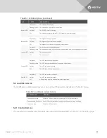
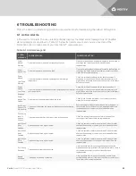
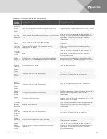
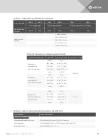
The power, battery, charger, system-control and system-monitor module have two LEDs each to indicate
the module operating state. The location of the LED is shown in the description of each module in
on page 16, and Table 6.2 below describes the meaning the LED indicators.
GREEN STATUS LED
YELLOW FAULT LED
DESCRIPTIONS OF MODULE STATE
Off
Off
The module is not inserted into the frame, lock lever is in unlocked position or the
system is off
Off
On
The module is initializing (maximum 30 seconds
1
)
Flashing
Off
The module is operating normally
Flashing
Flashing
The module is in startup mode or the module has an alarm
2
Flashing
On
The module is faulty and off-line, and the control module is operating
Off
Flashing
The module is not operating correctly, re-insert the module. If this persists, contact
technical support personnel.
On
Off
On
On
On
Flashing
1. If this condition persists for more than 30 seconds, verify that the lock lever is in the locked position. If it is not, the module is faulty.
2. If both green and yellow LEDs are flashing for more than 30 seconds, reinsert module.
Table 6.2 Descriptions of module LEDs
6.3 Module Replacement
Follow these instructions when replacing or adding a system-control, system-monitor, power, battery, or
charger module. Contact your Vertiv™ representative to purchase additional modules to expand your
system or for replacement modules.
6.3.1 Removing Power, Battery and Charger Modules
WARNING! Risk of heavy unit falling over. Can cause equipment damage, injury or death. Read
all of the instructions before attempting to move the unit, lift it, remove packaging or prepare
the unit for installation. The UPS presents a tipping hazard. Do not remove more than one
module at a time. Failure to do so may cause unit to tip over and cause serious injury.
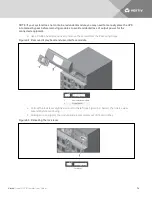
1. Remove bezel cover to locate the faulty module. The yellow fault LED is illuminated on the
faulty module.
NOTE: When removing bezels from a transformer-based UPS, note which have filters and replace them
accordingly. Bezels from the modules have air filters. There are no filters on the bottom three
transformer bezels. The transformer has a separate air filter.
NOTE: If your system does not contain a redundant module, you may need to manually place the UPS
into manual bypass before removing modules to avoid accidental loss of output power for the
connected equipment.
Vertiv
| Liebert® APS™ Installer/User Guide |
72
Summary of Contents for Liebert APS series
Page 1: ...Liebert APS 5 20 kVA Modular UPS Installer User Guide...
Page 6: ...Vertiv Liebert APS Installer User Guide 6...
Page 10: ...Vertiv Liebert APS Installer User Guide 10 This page intentionally left blank...
Page 50: ...Vertiv Liebert APS Installer User Guide 50 This page intentionally left blank...
Page 76: ...Vertiv Liebert APS Installer User Guide 76 This page intentionally left blank...
Page 80: ...Vertiv Liebert APS Installer User Guide 80 This page intentionally left blank...
Page 109: ......

