8.2.2 Control Mode
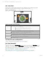
The water valve is controlled according to temperature (supply air temperature, return air temperature, and remote
temperature) and humidity (supply air humidity, return air humidity, and remote humidity).
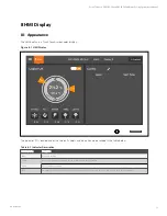
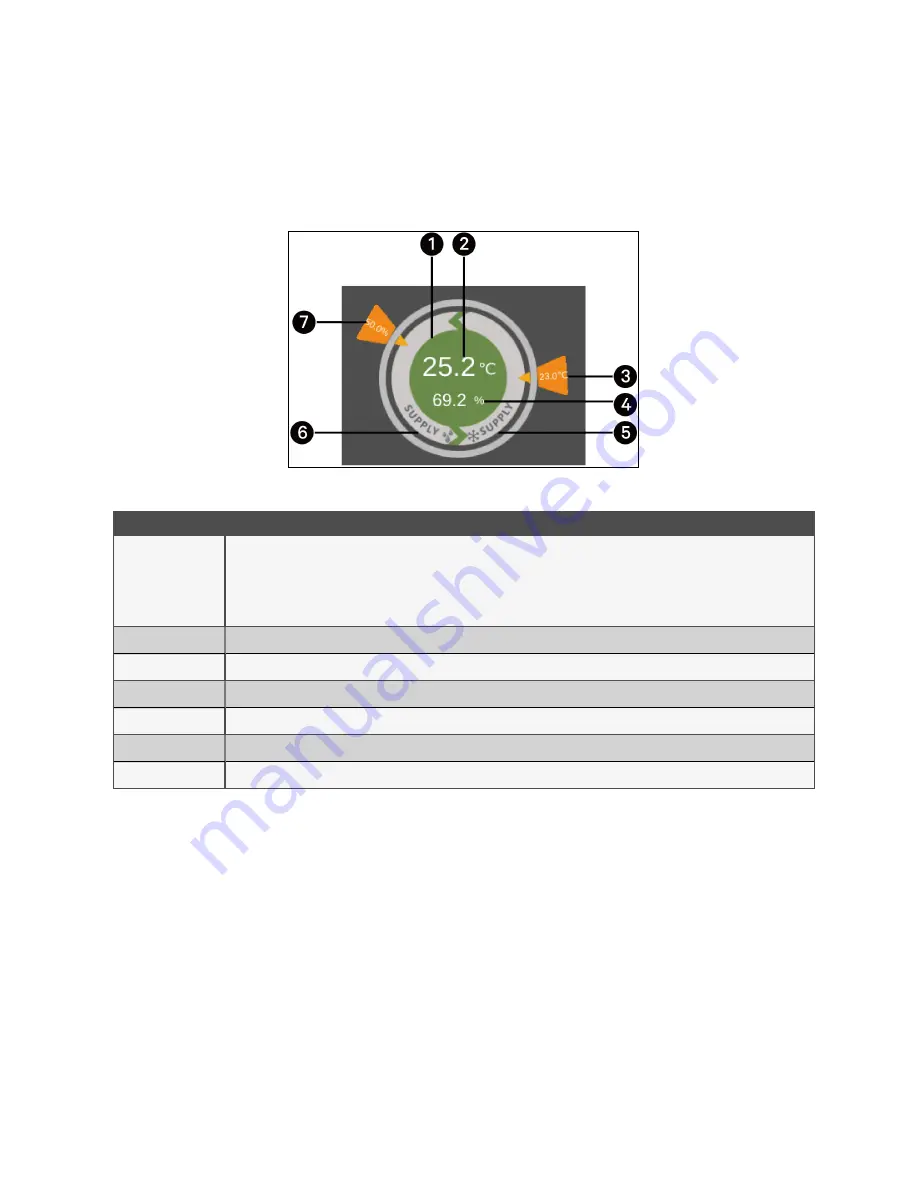
Figure 8.4 Control Mode Diagram
1
The color of this area indicates the status of the unit:
•
Green: The unit is On and the temperature is within normal range
•
Red: The unit is On and the temperature is not within normal range
•
Grey: The unit is Off
2
Supply air temperature, return air temperature, or remote temperature, depending on the control mode
3
Desired supply air temperature, return air temperature, or remote temperature set by user
4
Theoretical supply air humidity calculated according to current data
5
Control mode: chilled water valve is controled according to supply air temperature, return air temperature, or remote temperature
6
Control mode: chilled water valve is controled according to supply air humidity
7
Desired humidity set by user
Table 8.3 Description of Control Mode Diagram
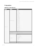
8.3 Menu Structure and Parameters
For menu structure and parameters, please refer to
8.4 Alarm Information
Press the menu button and choose Alarm Information to check active alarms and historical alarms. Active Alarms show the
active alarms and the time they are generated. Historical Alarms show active alarms and historical alarms, and the time
they are generated and closed (if the alarm has been resolved).
on page 71 lists all the alarms.
NOTE: Alarms are displayed in time sequence, starting with the latest one.
NOTE: Up to 500 historical alarms can be stored. They will not be cleared when unit is powered off.
8 HMI Display
54
Vertiv™ Liebert® CRV CRC30 and CRC60 Chilled Water Cooling System User Manual

