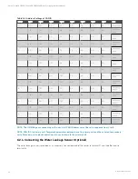
CAN ID
SW3-1
SW3-2
SW3-3
SW3-4
SW3-5
SW3-6
SW3-7
SW3-8
Note
0
ON
ON
ON
ON
ON
ON
ON
ON
Primary Unit
1
OFF
ON
ON
ON
ON
ON
ON
ON
Secondary
Unit 1
2
ON
OFF
ON
ON
ON
ON
ON
ON
Secondary
Unit 2
3
OFF
OFF
ON
ON
ON
ON
ON
ON
Secondary
Unit 3
4
ON
ON
OFF
ON
ON
ON
ON
ON
Secondary
Unit 4
5
OFF
ON
OFF
ON
ON
ON
ON
ON
Secondary
Unit 5
6
ON
OFF
OFF
ON
ON
ON
ON
ON
Secondary
Unit 6
7
OFF
OFF
OFF
ON
ON
ON
ON
ON
Secondary
Unit 7
8
ON
ON
ON
OFF
ON
ON
ON
ON
Secondary
Unit 8
9
OFF
ON
ON
OFF
ON
ON
ON
ON
Secondary
Unit 9
10
ON
OFF
ON
OFF
ON
ON
ON
ON
Secondary
Unit 10
11
OFF
OFF
ON
OFF
ON
ON
ON
ON
Secondary
Unit 11
12
ON
ON
OFF
OFF
ON
ON
ON
ON
Secondary
Unit 12
13
OFF
ON
OFF
OFF
ON
ON
ON
ON
Secondary
Unit 13
14
ON
OFF
OFF
OFF
ON
ON
ON
ON
Secondary
Unit 14
15
OFF
OFF
OFF
OFF
ON
ON
ON
ON
Secondary
Unit 15
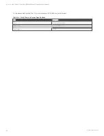
Table 6.2 Address Settings of CAN ID
NOTE: The iCOM Edge can connect up to 16 units. Unit CAN ID address must be set in sequence from 0 to 15.
NOTE: CAN ID 0 is primary unit. Teamwork parameters only can be set in primary unit and then shared to secondary
units. Secondary unit uploads operation status and alarms to the primary unit.
6.2.4 Connecting the Water Leakage Sensor (Optional)
The water leakage sensor is provided as an accessory. Connect one end of the sensor to terminal 51 and the other end to
terminal 24.
6 Electrical Connections
44
Vertiv™ Liebert® CRV CRC30 and CRC60 Chilled Water Cooling System User Manual

