Vertiv
| Liebert
®
EXM
™
EBC
™
480V User Manual |
7
NOTICE
Risk of failure to properly charge batteries. Can cause permanent damage to batteries and void the
warranty.
Batteries will self-discharge during storage. Batteries must be recharged as recommended by the battery
manufacturer.
A notice of “Charge Before Date” is affixed to each unit that has batteries inside. The “Charge Before
Date” is calculated based on the batteries being stored at 77°F (25°C). Storage at a higher temperature
will increase the rate of self-discharge, requiring earlier recharge. Consult the battery manufacturer on
how to determine when the batteries need to be recharged.
1.4.3 Installation Considerations
Position
—Refer to UPS manual (SL-26102 for 50-250kVA units) or submittals for complete
system line-up details. Liebert EXM Battery Cabinet(s) are designed to be located next to each
UPS module on the left side only and are also available in stand-alone configurations with painted
side panels. The front access design eliminates side and rear service clearance requirements.
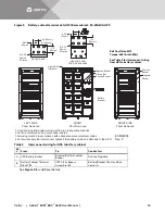
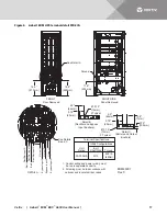
Refer to
for battery cabinet dimensions and weights.
Bolt-On Cabinets
—Matching battery cabinets are designed to bolt only onto the left side of the
UPS module cabinet. Use bolts that ship with each unit to connect cabinet frames at posts, two
places in the front and two places in the rear.
Service Clearance
—Allow front access to the battery cabinet at all times for maintenance and
service. Electrical codes require that the battery cabinet be installed with no less than 3 ft. (1m) of
clearance at the front of the cabinet when operating. No service clearance is required on either
the side or rear. Clearance at the top of the cabinet is 24" (610mm).
Cables (50-250kVA Units)
—Cables may be run between the cabinets through cutouts in the
top of the cabinet, eliminating the need for external conduit runs. Route cables before moving
cabinets into final position for bolting together. No top or bottom entry cables are required,
except for remotely located cabinets which require conduits.
Power terminals, auxiliary terminals blocks and circuit breakers are accessed from the front and
top.
Removable panels on the top are secured to the chassis by screws. The door can be opened to
give access to the power connections bars, auxiliary terminal blocks and breakers. The front door
can be opened 180° for easier service and more flexibility in installation.
Software
—To allow the UPS to accurately display the battery run time, the number of battery
cabinets must be noted when performing initial startup and setup using the configuration
software. This is to be performed by the Vertiv engineer when commissioning the unit.
Casters and Adjustable Stops
—The adjustable stops are not designed to bear the full weight of
the cabinet. Lower the stops until they are finger-tight in contact with the floor. Then tighten a
small amount with a wrench (less than two turns) to give a good friction fit. When mounting the
battery cabinet on seismic stands, ensure that the casters are bearing the weight of the cabinet.


