background image

Vertiv

| Liebert

®

 EXM

 EBC

 480V User Manual  |  

27

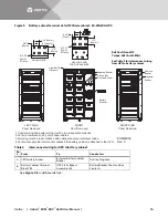
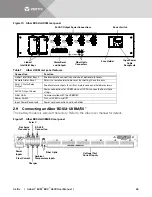
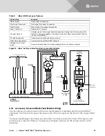
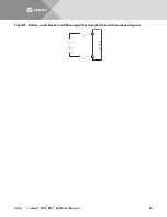
Figure 12 Alber

®

 battery cabinet monitoring assembly diagram

2.9.1

Accessory Fuses and Back-Feed Breaker Wiring

Two fuse blocks provide power for the back-feed breakers (standard) and the Alber BDSUi


(optional). The fuse blocks are at the lower right of the I/O panel on the front of the Liebert EXM 
UPS.
The back-feed breaker fuse block provides 120V nominal provided from the UPS output (L-N) 
and the fuse is rated for 8 amps. The back-feed breaker wiring is on the bypass static switch 
assembly.

Table 8

Alber UXCM rear panel features

Connection

Function

Power Inputs

Power Input Connections

Discharge Transducer

Discharge Transducer Connection

Float Current

Float Current Transducer Connection

Form C Contacts

Spare Form C Contacts

Charger Contact

Charger contact for charger control connection. Charger control relay output for 
thermal runaway management. (Automatically shuts down charger when thermal 
runaway is detected.)

RS-485 Connection

Communication with optional accessories

Fiber Optic Connectors

Communication with the BDSU network

Voltage/Test Current 
Inputs

Sense lead connections for making voltage/test current measurements

Connections to Battery Trays

Temperature
Sensor

Current
Transformer

T

o

 T

ray #3 (Jars 16-18)

T

o

 T

ray #3 (Jars 13-15)

T

o

 T

ray #4 (Jars 22-24)

T

o

 T

ray #4 (Jars 19-21)

T

o

 T

ray #2 (Jars 10-12)

T

o

 T

ray #2 (Jars 7-9)

T

o

 T

ray #1 (Jars 4-6)

T

o

 T

ray #1 (Jars 1-3)

J5

J4

J3

J2

J1

Temperature 1

Transducers-Current

TB2

Blue

Brown

Brown

White

Green

Black

Red

Yellow/Green

RX TX

Fiber Optic

RX TX

Fiber Optic

24VAC

24VAC

115VAC

Input

BDSUi-BATTERY MODULE

BDSUi-Control

See Diagram

at Right

AC 480V

From UPS

113

TB2

XFMR

531371G1

115  x3

AC 120V

(To Alber Controller)

Option: Power for Alber System

Blue

Brown

Yellow/Green

White

Black

12

H4

X4

X2

X3

X1

H2

H3

H1

608757
Rev. 0

607255
Pg. 4, Rev. 0

Summary of Contents for Liebert EXM 480V

Page 1: ...Liebert EXM 480V External Battery Cabinet User Manual...

Page 2: ...r damages resulting from use of this information or for any errors or omissions Refer to other local practices or building codes as applicable for the correct methods tools and materials to be used in...

Page 3: ...12 2 2 1 Connected System 12 2 2 2 Stand Alone and Right Mounted Systems 12 2 2 3 Grounding 12 2 3 Control Connection 13 2 4 Non Standard Batteries 13 2 5 Batteries Approved for Use in Liebert EXM Sy...

Page 4: ...ents 1200mm cabinet 27 Figure 15 Battery circuit breaker and UPS wiring with external batteries with two connecting wires31 TABLES Table 1 Control wiring for Liebert EXM to battery cabinet 9 Table 2 I...

Page 5: ...prior to moving a battery cabinet after initial installation Battery cabinets contain non spillable batteries Keep units upright Do not stack Do not tilt Failure to heed this warning could result in...

Page 6: ...ordance with federal state and local regulations Because lead is a toxic substance lead acid batteries must be recycled rather than discarded Do not dispose of battery or batteries in a fire The batte...

Page 7: ...r ni percer les batteries car l lectrolyte qui s en coulerait est nocif pour la peau et les yeux Cet lectrolyte est toxique Lorsque vous travaillez avec des batteries prenez les pr cautions suivantes...

Page 8: ...tion AVERTISSEMENT Le centre de gravit lev de l appareil pr sente un risque de renversement Une mauvaise manutention peut entra ner des dommages mat riels des blessures et m me la mort Faites preuve d...

Page 9: ...electrician All power and control wiring must comply with all applicable national state and local codes One person should never work alone even if all power is disconnected from the equipment A secon...

Page 10: ...ere are signs of damage do not proceed Call Vertiv at 1 800 542 2378 Report any damage to the shipper immediately Verify that the correct equipment is being installed The equipment supplied has an ide...

Page 11: ...r maintenance and service Electrical codes require that the battery cabinet be installed with no less than 3 ft 1m of clearance at the front of the cabinet when operating No service clearance is requi...

Page 12: ...aised floor it should be mounted on a pedestal suitably designed to accept the equipment point loading Refer to the base view to design this pedestal WARNING Risk of heavy unit falling over Improper h...

Page 13: ...3 Remove the battery cabinet front panel to gain access to the busbars 4 Connect the safety ground and any necessary bonding ground cables to the copper ground busbar example UPS located behind the o...

Page 14: ...ioned 6 Connect TB1 from battery cabinet to J22 on the UPS according to Table 1 Figure 2 Bolting the Liebert EXM Battery Cabinet to the Liebert EXM UPS NOTE The shunt trip drive capability for the bat...

Page 15: ...ling for 50 250kVA UPS 50 250kVA Liebert eXM Battery Cabinet 1 Battery Cabinet 2 Battery Cabinet 3 Battery Cabinet 4 DC Input Busbar See Table 10 for power cable Battery cabinet placement is critical...

Page 16: ...Regular maintenance of the battery module is an absolute necessity Periodic inspections of battery and terminal voltages specific gravity and connection resistance should be made Strictly follow the...

Page 17: ...ed remove source of ground Contact with any part of a grounded battery can result in electrical shock Battery support tray must be used whenever a battery tray is being pulled out 2 1 1 Connecting the...

Page 18: ...7 Control Wiring See Figure 9 and Table 1 for control wiring between the Liebert EXM Battery Cabinet and the Liebert EXM UPS See Figures 4 through 7 for battery cabinet terminal details 2 4 Non Stand...

Page 19: ...ttery Battery Breaker 62 4 1585mm Alber BDSUi Optional LEFT SIDE Panel Removed RIGHT SIDE Panel Removed FRONT Door Removed 1 Control wiring and power wiring must be run in separate conduits 2 Vertiv r...

Page 20: ...ces 0 56 14mm 6 Places 0 85 22mm 0 85 22mm Negative Busbar NEGATIVE AND POSITIVE BUSBARS Positive Busbar Negative Busbar Positive Busbar Ground Bus GROUND BUS Battery Breaker Alber BDSUi Optional LEFT...

Page 21: ...See Detail A EXM46001 Rev 0 17 9 455mm 0 15 13mm 3 Typical 0 15 13mm 2 Typical 18 5 470mm 18 8 480mm 0 75 195mm Rectifier Input C Batt Batt Rectifier Input B Rectifier Input A Bypass Input A Output A...

Page 22: ...tery Battery Bypass Input A Output A Output B Output C Bypass Input B Bypass Input C 1 Control wiring and power wiring must be run in separate conduits 2 All wiring must be in accordance with national...

Page 23: ...punch holes for fitting and securing the conduit Once the conduit holes are punched these plates should be reattached to the UPS The conduit size and wiring method must be in accordance with all loca...

Page 24: ...Block at J22 Refer to Figure 9 for circuit details Table 5 Battery cabinet interface J22 Pin Name Description 1 12V_DRV BCB driver signal 3 BCB STATUS BCB state signal 5 GND_DRY Dry ground 7 BCB_ON B...

Page 25: ...le the recorded float voltage should be within the range shown If a discrepancy is found contact Vertiv Power Connections Check for corrosion and connection integrity Inspect wiring for discolored or...

Page 26: ...Disconnect and insulate the cables connected to the battery Secure each battery shelf with retaining screws when maintenance is complete WARNING Risk of heavy unit tipping over while being moved Can c...

Page 27: ...d and recycled or discarded in accordance with federal state and local regulations Because lead is a toxic substance lead acid batteries must be recycled rather than discarded Do not dispose of batter...

Page 28: ...vinciaux et municipaux tant donn que le plomb est une substance toxique les batteries au plomb acide doivent tre recycl es plut t que mises au rebut Ne jetez jamais de batteries au feu car elles risqu...

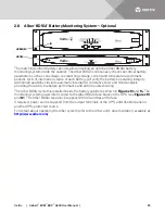
Page 29: ...pabilities include automatic internal DC resistance tests and trend analysis providing the ability to analyze performance and aid in troubleshooting The Alber BDSUi system is installed inside the batt...

Page 30: ...wer Power connections for UXBM when a UXCM is connected to multiple strings Fiber Optic Communication with the UXBM 50 Power Switch Turns UXCM On and Off Input Power Receptacle Power cord connection a...

Page 31: ...r control connection Charger control relay output for thermal runaway management Automatically shuts down charger when thermal runaway is detected RS 485 Connection Communication with optional accesso...

Page 32: ...e UPS output L N and the fuse is rated at 8A See Figure 12 for the Alber BDSUi power wiring 2 10 Battery Protection 2 10 1 Battery Low Voltage Warning Before the end of discharge the Liebert EXM displ...

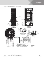
Page 33: ...haust 36 914mm frtont access required for service 2 Keep cabinet within 15 degrees of vertical 3 Top and bottom cable entry available through removable access plates Remove punch to suit conduit size...

Page 34: ...Vertiv Liebert EXM EBC 480V User Manual 30 Figure 14 Battery cabinet outline and main components 1200mm cabinet...

Page 35: ...e access plates Remove punch to suit conduit size and replace 4 Control wiring and power wiring must be run in separate conduits 5 Copper cables only are recommended 6 All wiring must be in accordance...

Page 36: ...70 C 74 F to 80 F 23 27 C for optimal battery life Operating Temperature Range F C 32 F to 104 F 0 to 40 C 74 F to 80 F 23 27 C for optimal battery life Relative Humidity up to 95 Non Condensing Oper...

Page 37: ...04 HR4000 5429 31HR5000 3987 HR5500 5145 C D UPS12 150MR 2500 UPS12 210MR 3000 UPS12 300MR 3600 UPS12 350MR 4200 UPS12 400MR 5100 UPS12 490MR 5000 UPS12 540MR 5000 Table 12 Battery DC intermediate cir...

Page 38: ...le 8 30 hr Boost charge mode inhibit also selectable End of Discharge 1 67 V cell selectable from 1 67 1 750V cell Battery Charge Operation Constant current and constant voltage charge mode Programmab...

Page 39: ...k Protection Degree IEC 60529 IP20 finger proof with front doors open or closed Table 14 1200mm battery cabinet mechanical characteristics Rated Power kVA 50 250kVA Dimensions W x D x H in mm 34 645 x...

Page 40: ...Vertiv Liebert EXM EBC 480V User Manual 36 Figure 15 Battery circuit breaker and UPS wiring with external batteries with two connecting wires U P S...

Page 41: ...e log to record scheduled checks and any abnormal conditions The log should have space for all metered data including phase readings alarm messages UPS mode of operation air filter replacement date an...

Page 42: ...cordance with federal state and local regulations Because lead is a toxic substance lead acid batteries must be recycled rather than discarded Do not dispose of battery or batteries in a fire The batt...

Page 43: ...er pour l installation Les responsables de l entretien et l quipement d essai doivent reposer sur des tapis de caoutchouc lors de toute intervention sur une pi ce d quipement sous tension Les batterie...

Page 44: ...turer s Web site for specific information about equalize charging AVERTISSEMENT Risque de d charge lectrique de r action explosive d incendie et d exposition des produits chimiques dangereux pouvant e...

Page 45: ...1 3 HR3500 100 11 3 HR4000 100 11 3 31HR5000 100 11 3 HR5500 100 11 3 C D UPS12 150MR 30 3 4 UPS12 210MR 30 3 4 USP12 300MR 110 12 4 UPS12 350MR 110 12 4 UPS12 400MR 110 12 4 USP12 490MR 110 12 4 UPS1...

Page 46: ...Vertiv Liebert EXM EBC 480V User Manual 42 NOTES...

Page 47: ...Vertiv Liebert EXM EBC 480V User Manual 43...

Page 48: ...Vertiv Liebert EXM EBC 480V User Manual 44...

Page 49: ......

Page 50: ...mes and logos referred to are trade names trademarks or registered trademarks of their respective owners While every precaution has been taken to ensure accuracy and completeness herein Vertiv Co assu...

Reviews: