Vertiv
| Liebert
®
EXM
™
Battery Cabinet User Manual |
17
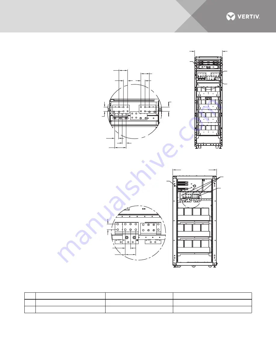
Figure 5
Battery cabinet terminal detail, 600mm and 880mm cabinet; 10-120kVA UPS
See
Figure 9
for additional details.
Table 2
Interconnect wiring for UPS to battery cabinet
Run From
To
Conductors
A
UPS Battery Busbar
External Battery Cabinet Busbar
Positive, DC Neutral, Negative
B
Battery Cabinet Terminal Block TB1
UPS Static Bypass Assembly J22
Battery Breaker Shunt and Aux Contacts
FRONT
Door Removed
23.6"
(600mm)
DC
Connection
Busbars
Ground
Bus
Detail A
See Detail A
EXM16004
Rev. 0
3.66"
(93mm)
3.66" (93mm)
1.75"
(45mm)
1.75"
(45mm)
1.65"
(42mm)
4.96"
(126mm)
1.65" (42mm)
1.75" (45mm)
1.75"
(45mm)
600mm Battery Cabinet
RIGHT SIDE
Panel Removed
37.5" (953mm)
DC Connection
Busbars
Ground
Bus
Detail A
See Detail A
EXM16004
Rev. 0
3.3" (84mm)
1.75" (45mm)
1.65" (42mm)
880mm Battery Cabinet
1. Control wiring and
power wiring must
be run in separate
conduits.
2. Vertiv recommends
using only copper
cables.
3. All wiring must be
in accordance with
national and local
electrical codes.
4. Interconnection
cables factory-
supplied if the
battery cabinet is
attached to the left
side of the UPS.
Bolt Shaft Size: M12
Torque: 428 lb-in (48Nm)
Bolt Shaft Size: M12
Torque: 428 lb-in (48Nm)


