Vertiv
| Liebert
®
ITA2
™
User Manual |
7
1.4.1
Transient Voltage Surge Suppression (TVSS) and EMI/RFI Filters
These UPS components provide surge protection and filter both electromagnetic interference
(EMI) and radio frequency interference (RFI). They minimize any surges or interference present
in the mains line and protect the sensitive equipment even when on internal bypass power.
1.4.2 Rectifier/Power Factor Correction (PFC) Circuit
In normal operation, the rectifier/power factor correction (PFC) circuit converts mains AC power
to regulated DC power for use by the inverter while ensuring that the wave shape of the input
current used by the UPS is near ideal. Extracting this sine wave input current:
•
Ensures efficient use of the mains power.
•
Reduces distortion reflected on the mains.
This makes cleaner power available to other devices in the building not protected by the Liebert
ITA2.
1.4.3 Inverter
In normal operation, the inverter utilizes the DC output of the power factor correction circuit and
inverts it into precise, regulated sine wave AC power. When mains power fails, the inverter
receives energy from the battery through the DC-to-DC converter. In both normal mode and
bypass mode, the UPS inverter remains on-line, generating clean, precise, regulated AC output
power.
1.4.4 DC-DC Charger
Whenever the Liebert ITA2 is connected to utility power and the rectifier is operating, the battery
charger receives energy through the internal DC bus (output of rectifier/PFC) and regulates it to
continuously float charge the batteries.
1.4.5 Static Bypass Switch
The Liebert ITA2 static bypass switch provides an alternate path for utility power to the
connected equipment should the UPS have an output overload, overtemperature condition or
any other failure. When UPS output power fails, the Liebert ITA2 automatically transfers the
connected equipment to bypass power through the static bypass.
1.4.6 Battery Cabinets
The Liebert ITA2 utilizes valve-regulated, non-spillable, lead-acid batteries. To maintain battery
design life, operate the UPS in an ambient temperature of 68°F to 77°F (20°C to 25°C). Additional
battery cabinets are available to extend battery run times. For run times, see
1.5
UPS State and Operation Mode
For the LED indicators introduced in this section, refer to
.
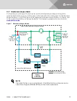
The UPS state and operation mode include: Normal Mode, Bypass Mode, Battery Mode, ECO
Mode, Fault state and Maintenance Bypass Mode. The operation schematic diagrams of Normal
Mode, Bypass Mode, Battery Mode and Maintenance Bypass Mode are shown in
through
NOTE
Maintenance Bypass Mode is available only when the UPS system includes the optional MBC
cabinet.
Summary of Contents for Liebert ITA2-08KRT208
Page 1: ...Liebert ITA2 8 10kVA 60Hz 208 220V Three Phase UPS User Manual...
Page 40: ...Vertiv Liebert ITA2 User Manual 34 Figure 31 Status page menus...
Page 70: ...Vertiv Liebert ITA2 User Manual 64 NOTES...
Page 71: ...Vertiv Liebert ITA2 User Manual 65...
Page 72: ...Vertiv Liebert ITA2 User Manual 66...
Page 73: ......


