


6.1 Line Voltage Wiring
WARNING! Risk of electrical fire and short circuit. Can cause property damage, injury or death. Select and
install the line side electrical supply wire and overcurrent protection device(s) according to the specifications
on the unit nameplate(s), per the instructions in this manual and according to the applicable national, state
and local code requirements. Use copper conductors only. Verify that all electrical connections are tight. Unit
specific wiring diagrams are provided on each unit.
Risk of improper power supply connection. Can cause equipment damage and loss of warranty coverage.
Prior to connecting any equipment to a main or alternate power source (for example: backup generator
systems) for startup, commissioning, testing, or normal operation, ensure that these sources are correctly
adjusted to the nameplate voltage and frequency of all equipment to be connected. In general, power source
voltages should be stabilized and regulated to within ±10% of the load nameplate nominal voltage. Also, ensure
that no three phase sources are single phased at any time.
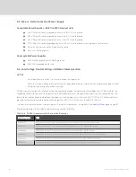
NOTE: For acceptable and unacceptable power supplies, see
Wye vs. Delta Connected Power Supply
Condenser rated voltage should be verified with available power supply before installation. Refer to the unit’s electrical
schematic and serial tag for specific electrical requirements.
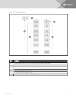
Liebert® MC condenser power connections are provided for three-phase wires and 1 earth ground wire. Line voltage
electrical service is required for all condensers at the location of the condenser. The voltage supply to the condenser may
not be the same voltage supply as required by the indoor unit. Consider using a UPS on both indoor cooling units and MC
condensers to maintain uninterrupted cooling capability. Refer to the unit’s serial tag for specific condenser electrical
requirements. A unit disconnect is standard. However, a site disconnect may be required by local code to isolate the unit for
maintenance. Route the supply power to the site disconnect switch and then to the unit. Route the conduit to the knockout
provided in the bottom-right end of the electrical control enclosure. Connect the earth ground wire lead to the marked earth
ground connection terminal provided near the factory installed disconnect switch per the appropriate drawing in the
NOTE: A separate neutral wire does not need to be run to the Liebert® MC condenser.
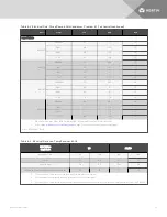
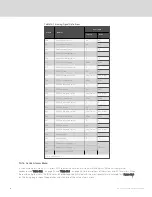
6.2 Electrical Power Requirements
Table 6.2 on the next page lists the power requirements by model number and size. Table 6.3 on page 37 lists the
additional electrical requirements if your system includes a Liebert® Lee-Temp receiver.
6 Electrical Connections
35
Summary of Contents for Liebert MC series
Page 1: ...Liebert MC Installer User Guide 60 Hz Air Cooled Microchannel Condenser Premium EC Fan ...
Page 8: ...Vertiv Liebert MC Installer User Guide 4 This page intentionally left blank ...
Page 14: ...Vertiv Liebert MC Installer User Guide 10 This page intentionally left blank ...
Page 28: ...Vertiv Liebert MC Installer User Guide 24 This page intentionally left blank ...
Page 44: ...Vertiv Liebert MC Installer User Guide 40 This page intentionally left blank ...
Page 46: ...Vertiv Liebert MC Installer User Guide 42 This page intentionally left blank ...
Page 48: ...Vertiv Liebert MC Installer User Guide 44 This page intentionally left blank ...
Page 76: ...Vertiv Liebert MC Installer User Guide 72 This page intentionally left blank ...
Page 88: ...Vertiv Liebert MC Installer User Guide 84 This page intentionally left blank ...
Page 90: ...Vertiv Liebert MC Installer User Guide 86 This page intentionally left blank ...


