


11.4 Replacing the Premium Efficiency Control Board
Use these steps to replace the premium efficiency control board in the condenser.
WARNING! Arc flash and electric shock hazard. Open all local and remote electric power supply disconnect
switches, verify with a voltmeter that power is Off and wear appropriate, OSHA approved personal protective
equipment (PPE) per NFPA 70E before working within the electric control enclosure. Failure to comply can
cause serious injury or death. Customer must provide earth ground to unit, per NEC, CEC and local codes, as
applicable. Before proceeding with installation, read all instructions, verify that all the parts are included and
check the nameplate to be sure the voltage matches available utility power. The Liebert® controller does not
isolate power from the unit, even in the “Unit Off” mode. Some internal components require and receive
power even during the “Unit Off” mode of the controller. The factory supplied disconnect switch is inside the
unit. The line side of this switch contains live high voltage. The only way to ensure that there is NO voltage
inside the unit is to install and open a remote disconnect switch. Refer to unit electrical schematic. Follow all
local codes.
11.4.1 Preparing to Replace the Board
1.
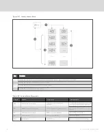
Verify that the following jumpers are installed on the new board (see Figure 11.4 on the facing page):
•
Jumper at J4 and J6 on Pins 2 and 3.
•
Jumper on J2.
•
Jumper on J5 on Pins 1 and 2.
2.
Locate the latest revision of the HMI parameters label, 303847P1, included with the new control board.
NOTE: In Figure 11.4 on the facing page, J6 is the CANbus termination jumper. J4 is the RS485 service termination
jumper. If the condenser is the last device in the CANbus communication line, the jumper must be placed between
Pins 1 and 2 of J6. If the condenser is not the last device in the CANbus communication line, the jumpers on J6 must
be placed on Pins 2 and 3. If the jumper is not in the correct positions, CANbus communication errors may occur. The
jumper on J4 will always be placed between Pins 1 and 2.
NOTE: In Figure 11.4 on the facing page, a jumper must be present at J2. If a jumper is not present, the control board
will not boot properly during power start-up.
Vertiv | Liebert® MC Installer/User Guide
66
Summary of Contents for Liebert MC series
Page 1: ...Liebert MC Installer User Guide 60 Hz Air Cooled Microchannel Condenser Premium EC Fan ...
Page 8: ...Vertiv Liebert MC Installer User Guide 4 This page intentionally left blank ...
Page 14: ...Vertiv Liebert MC Installer User Guide 10 This page intentionally left blank ...
Page 28: ...Vertiv Liebert MC Installer User Guide 24 This page intentionally left blank ...
Page 44: ...Vertiv Liebert MC Installer User Guide 40 This page intentionally left blank ...
Page 46: ...Vertiv Liebert MC Installer User Guide 42 This page intentionally left blank ...
Page 48: ...Vertiv Liebert MC Installer User Guide 44 This page intentionally left blank ...
Page 76: ...Vertiv Liebert MC Installer User Guide 72 This page intentionally left blank ...
Page 88: ...Vertiv Liebert MC Installer User Guide 84 This page intentionally left blank ...
Page 90: ...Vertiv Liebert MC Installer User Guide 86 This page intentionally left blank ...


