OVERVIEW
14
User Manual 10H52246UM60 - Rev. 1 - 01/2017
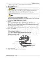
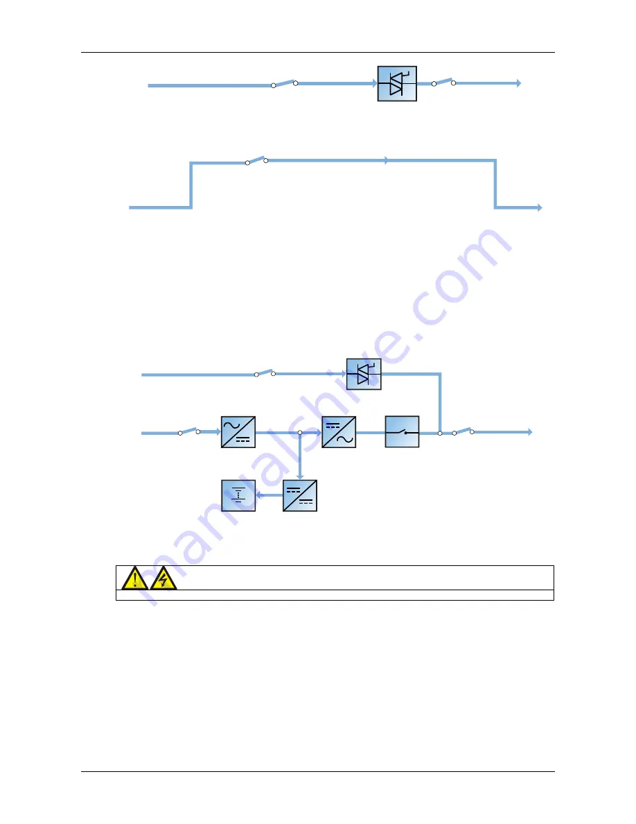
Bypass input switch
Bypass input
Static switch
Output switch
UPS output
Figure 1-5
Schematic diagram of bypass mode
Maintenance mode
As illustrated in Figure 1-6, if it is necessary to service the UPS or carry out maintenance work on it, the manual
maintenance bypass switch may be used to transfer the load to maintenance bypass, with no interruption in power
to the load. This maintenance bypass switch is fitted in all UPS modules and rated at the full load of one module.
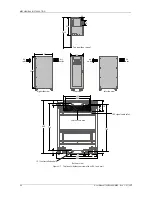
Maintenance bypass switch
Bypass input
Maintenance bypass
UPS output
Figure 1-6
Schematic diagram of maintenance mode
ECO mode
In ECO mode, UPS double-conversion operation is inhibited most of the time in order to save energy. In this
condition, the bypass is designated as the preferred source so that the critical AC load is transferred to the inverter
only when the bypass supply voltage and/or frequency is/are outside the pre-defined limits: if the inverter is
synchronized with the bypass source, the transfer will be instantaneous and during the transfer the output
waveform will not exceed the limits established by IEC/EN 62040-3 for a UPS to be classified as VFI-SS-111.
If the inverter is not synchronized with the bypass, in order to avoid hazardous cross current, the bypass/inverter
changeover is delayed for a few milliseconds (maximum 20ms) after the moment the bypass is disconnected from
the load. Then, once the bypass frequency and voltage have returned within the predefined limits for at least five
minutes, the load is automatically, and instantaneously, transferred back to the bypass line.
In this operating mode, the system can charge the battery as normal.
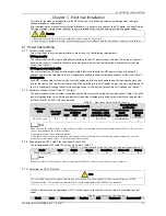
Bypass input switch
Rectifier input switch
Bypass input
Mains input
Battery charger
Output switch
Inverter
Rectifier
Static switch
UPS output
Battery
Automatic inverter switch
Figure 1-7
Schematic diagram of ECO mode
If ECO mode is selected, adjust the corresponding parameters via the operator control and display panel.
The ECO mode operating method is the same as described in Chapter 5
UPS Operation Introduction
. However, in
normal mode, the load is powered by the bypass, the inverter indicator flashes, the LCD displays 'Bypass mode', and
the transfer interval time is less than 20ms.
Warning
The load is not protected against distortion on the mains voltage waveform in ECO mode.
Parallel redundancy mode (system expansion)
In order to achieve higher capacity or higher reliability, or both, the outputs of multiple UPS modules can be
programmed for directly paralleling while a built-in parallel controller in each UPS module ensures automatic load
sharing. The parallel system can consist of up to four UPS modules. See Figure 7-1 for the diagram illustrating the
parallel redundancy operating principle.
LBS mode
A dual bus system consists of two independent UPS systems, each containing one or more UPS module connected
in parallel. The dual bus system provides high reliability and is suitable for connection to loads with multiple inputs.
Single-input loads may be supplied via an STS. See Figure 7-4 and Figure 7-5 for the diagram illustrating the LBS
operating principle.
Common battery string mode
In this case, when the UPS modules (up to four UPSs) are connected in parallel, each UPS module can use the same
battery string, thereby saving on costs and space.


