MECHANICAL INSTALLATION
User Manual 10H52246UM60 - Rev. 1 - 01/2017
21
charging process, connect the UPS to the mains temporarily and activate the battery by recharging it.
2.7
Mechanical Requirements
2.7.1
Moving the UPS
Warning
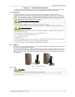
1. Ensure any any equipment used ot lift or move the UPS has sufficient lifting capacity.
2. The UPS is fitted with casters, take care to prevent it rolling away when removing it from the pallet. Ensure that the
available personnel and lifting equipment are sufficient to carry out this operation safely and correctly.
3. Due to the weight of the unit, the casters may be valid for moving it along flat surfacrs only.
4. The UPS has a high center of gravity, take precautions to prevent it from tipping over when moving it.
5. Never suspend the UPS in a vertical position.
Caution
When the batteries are already mounted in the cabinet, ensure that each battery string has been secured before attempting
to move it and make every effort to keep movement distances to a minimum.
Ensure that the UPS weight does not exceed the capacity of the lifting equipment. For UPS weight information, refer
to Table 11-3.
The UPS can be moved using a forklift or other similar lifting equipment.
The casters may be used when moving the UPS over short distances.
2.7.2
Clearance
The UPS has no lateral grills; therefore there are no special clearance requirements on the two sides.
In addition to the provisions of the local regulations, in order to enable routine tightening of the power terminals
within the UPS, we recommended that the clearance at the rear of the UPS be sufficient to enable the free passage
of personnel. In any event, as stated above, in order to allow heat to dissipate properly, there must be a space of at
least 200 mm between the rear of the UPS and the wall.
2.7.3
Cable Access Mode
The UPS is suitable for both top and bottom cable access configurations.
For more information, refer to
3.1.10
Power Cable Connection Steps
and 3.2.11
Signal Cable Connection Steps
.
2.7.4
Final Positioning And Fixing
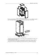
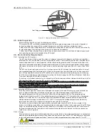
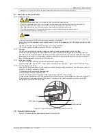
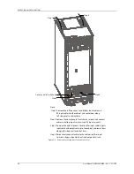
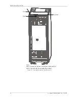
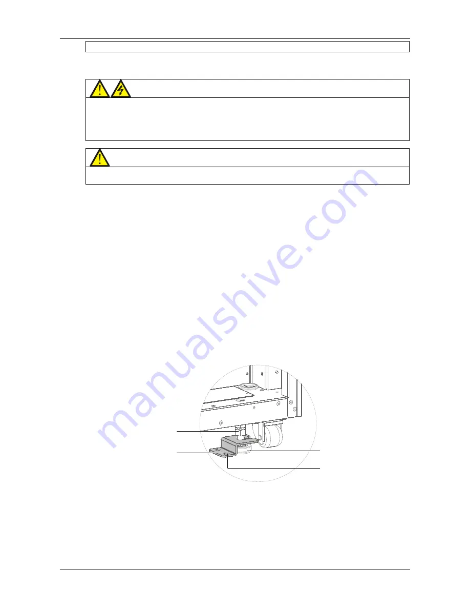
Once the UPS has been moved to its final position, use the four adjustable feet to secure it to the floor, as shown in
Figure 2-6. To do this, proceed as follows:
1. Loosen the nuts by unscrewing them upwards.
2. Rotate the feet until they touch the floor.
3. Fit the foot fixing pieces that were put aside when removing the UPS from its pallet.
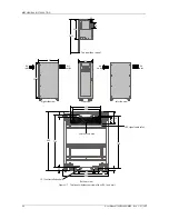
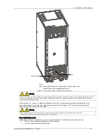
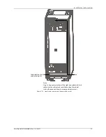
4. Align the foot fixing pieces with the pre-prepared installation holes, in with the dimensions indicated in Figure 2-7.
5. Rotate the nuts from top to bottom till they press firmly against the foot fixing pieces, and then use the M10
fixing bolts to secure the UPS to the floor.
Nut
Foot fixing piece
Foot
Installation hole
Figure 2-6
Diagram illustrating how to position and secure the UPS
2.8
Installation Drawings
Figure 2-7 illustrates the key mechanical characteristics of the UPS.


