ECLECTRICAL INSTALLATION
User Manual 10H52246UM60 - Rev. 1 - 01/2017
23
Chapter 3
Electrical Installation
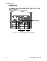
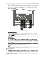
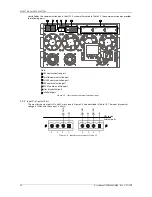
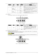
This chapter provides an introduction to the UPS electrical installation procedures, including power and signal
cabling procedures and methods.
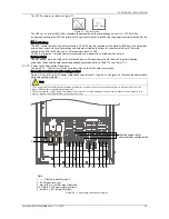
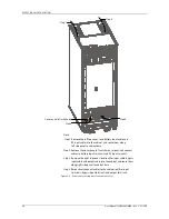
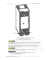
After completing the mechanical installation procedure, it is necessary to connect the UPS power and signal cables.
The signal cables, irrespective of whether they are shielded or not, must be kept away from the power cables.
Warning
1. Do not switch the UPS on before the authorized service engineer has arrived.
2. The UPS cables should be routed by an authorized engineer in accordance with the information contained in this chapter.
3.1
Power Cable Wiring
3.1.1
System Configuration
Select the size of the system power cables in order to satisfy the following requirements:
UPS input cable
The cable size of the UPS input cable differs according to the UPS power ratings and input AC voltages, and must
be selected so that it is capable of handling the maximum input current; including the maximum battery charge
current, see Table 3-1.
UPS bypass and output cable
The cable size of the UPS bypass and output cable differs according to the UPS power ratings and output AC
voltages, and must be selected so that it is capable of handling the nominal output or bypass current, see Table 3-1.
Battery cable
Each UPS is connected to its battery by the three cables, one for the positive pole, one for the negative pole, and
one for the neutral line. The battery cable size differs according to the UPS power ratings, and must be selected so
that it is capable of handling the battery discharge current as the battery reaches the EOD voltage, see Table 3-1.
3.1.2
Maximum Steady State AC And DC Currents
The power cable must be selected in accordance with the current and voltage values indicated in Table 3-1, and the
local wiring regulations, also taking environmental conditions (temperature and physical media) and the provisions
of Table 3B in IEC 60950-1 into consideration.
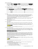
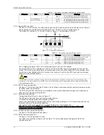
Table 3-1
Max. steady state AC and DC currents
UPS power
(kVA)
Rated current (A)
Bus stud bolt/nut
specification
Max. input
current
1,2
Output/bypass current
2
at full load
Battery discharge
current (+, -, N) at
min. battery voltage
Input/battery/o
utput/
bypass cable
Recommen
ded torque
(N.m)
380V
400V
415V
60 (3-in 3-out )
103
91
87
84
195/195/59
M6/M8/M6/M6
4.8/12/4.8/4
.8
When selecting the battery cables, a max. volt drop of 4Vdc is permissible at the current ratings given in Table 3-1. Do not form
coils, so as to minimize the formation of EMI.
1. Input mains current for rectifier and bypass.
2. Non-linear loads (such as switch-mode power supplies) affect the design of the output and bypass neutral line, since the
neutral line current may be up to 1.5 times the rated phase current.
3.1.3
Recommended UPS Cable Cross Sectional Area (CSA)
The recommended UPS cable CSA values are listed in Table 3-2.
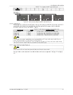
Table 3-2
Recommended UPS cable CSA (unit: mm
2
, ambient temperature: 25°C)
Model
Input
Output
Bypass
Neutral line
Earth cable
Battery
60kVA (3-in 3-out)
25
25
25
35
25
50
If the user’s cable CSA exceeds the value recommended in Table 3-2, please contact Vertiv service engineers.
3.1.4
Selecting the UPS I/O Switch
Note
The specified upstream breakers below are required to obtain the conditional short-circuit current rating, Icc at 10kA
symmetrical rms. The specified upstream breakers should comply with an IEC 60947 series standard.
Table 3-3 indicates the recommended UPS I/O switch capacity, so that the user can select it according to actual
needs.
Table 3-3
Selection of the UPS I/O switch
Model
Input
Recommended
Breaking
BCB
Output port
Recommended


