ECLECTRICAL INSTALLATION
User Manual 10H52246UM60 - Rev. 1 - 01/2017
27
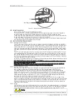
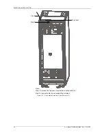
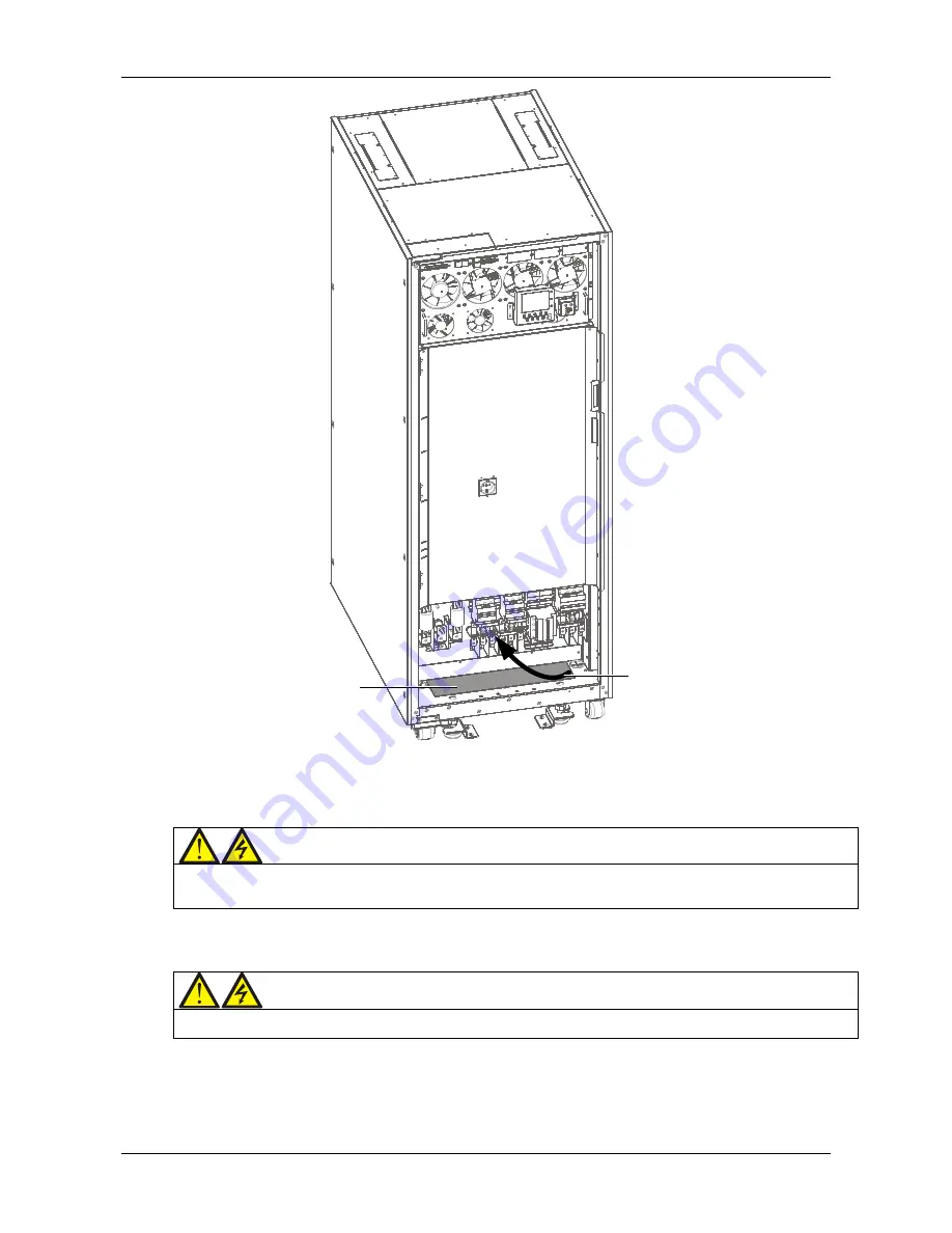
Step
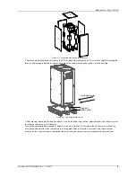
Bottom plate
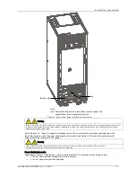
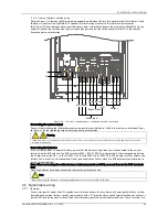
Step: Remove the bottom plate, lead cables into the cbainet and
Note:
connect them to corresponding terminals.
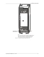
Figure 3-4
Power cables wiring route (bottom cable access)
Warning
Before connecting the cables, make sure that all external power switches are off, and position the necessary warning signs in order
to prevent inadvertent operation of the switches. Meanwhile, measure the voltages between the UPS terminals and the voltages
between the terminals and earth.
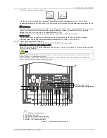
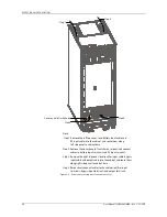
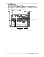
Refer to Figure 3-2 ~ Figure 3-4, open the front door of the UPS, and remove the protective cover (located at the
lower left corner) to reveal the power cable connection terminals (see Figure 3-2). Connect the protective earth
cable to the PE input terminal in the cabinet.
Warning
1. The earth cables and neutral line must be connected in accordance with local and national codes of practice.
2. Failure to observe this could result in electric shock or fire risk.
Power distribution mode
Depending on the user's requirements, there are two possible UPS I/O cable connection configurations:
3-in 3-out, common input configuration (factory default)
3-in 3-out, separate bypass configuration


