30
User Manual 10H52246UM60 - Rev. 1 - 01/2017
ECLECTRICAL INSTALLATION
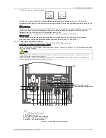
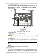
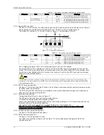
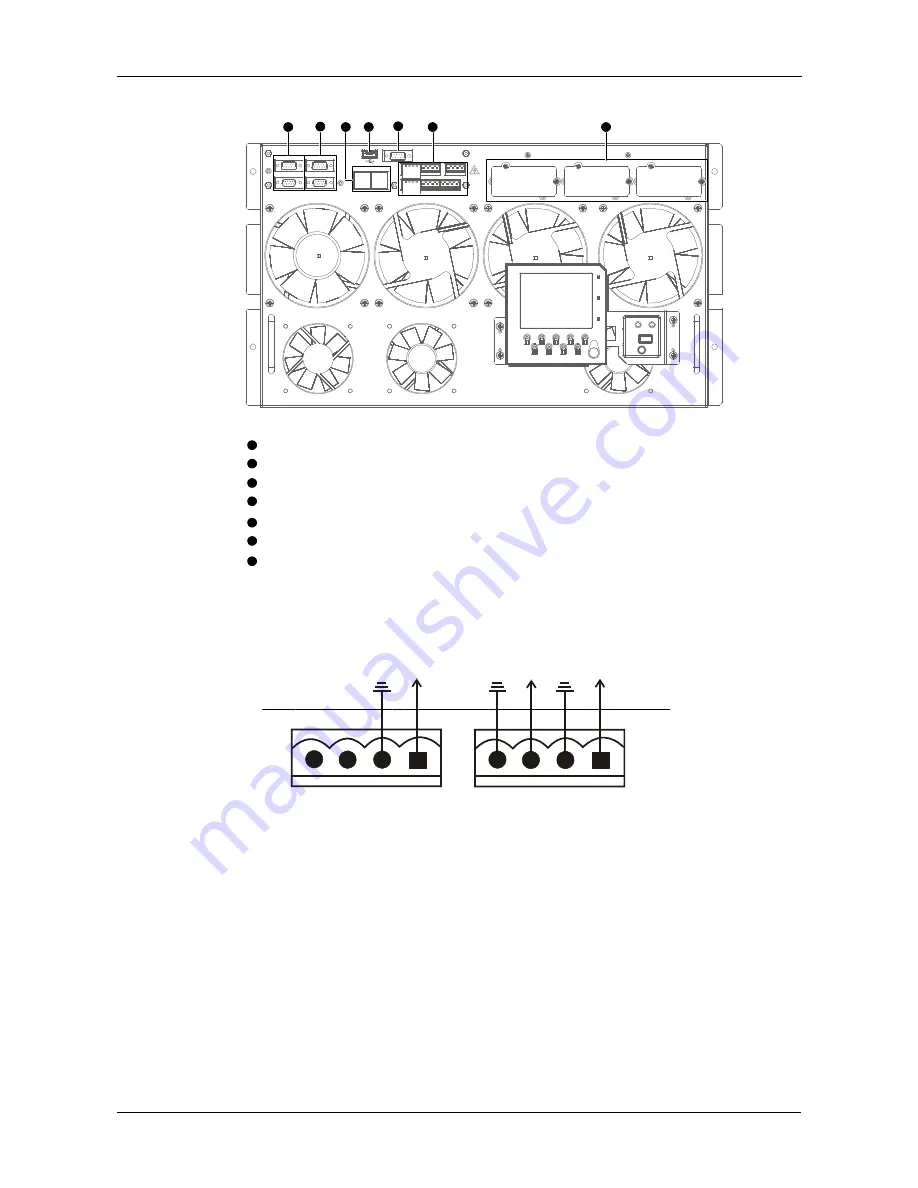
controlled by the communication box in the UPS. As shown illustrated in Table 3-7, the communication box provides
the following ports:
INTELLISLOT 1
INTELLISLOT 2
INTELLISLOT 3
RS485-1 RS485-2
USB
RS232
LBS 1
LBS 2
PARA 1
PARA 2
Note:
LBS communication port
Intellislot port
J1
J2
J3
J4
J5
J6
2
1
3
4
5
6
7
2
1
3
4
5
6
7
Parallel communication port
RS-485 communication port
USB communication port
RS232 communication port
User dry contact port
Figure 3-7
Illustration of communication box ports
3.2.2
Input Dry Contact Port
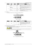
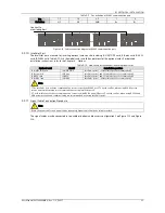
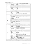
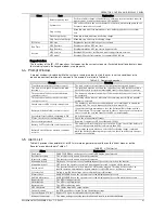
The input dry contact ports J1 and J5 are shown in Figure 3-8 and described in Table 3-5. The input dry contact
voltage is 12Vdc, and the current is 20mA.
GND
GND
GND
J1
J2
1
2
3
4
1
2
3
4
UPS inside
External ports
J1
J5
Figure 3-8
Input dry contact ports J1 and J5

