32
User Manual 10H52246UM60 - Rev. 1 - 01/2017
ECLECTRICAL INSTALLATION
Table 3-7
Description of backfeed protection dry contact port J3
Silkscreen
Port
Pin No.
Pin name
Meanings
J3
Rectifier/Bypass
backfeed output
3.2 BFP_O
Rectifier/bypass backfeed normally open
contact. Open when there is no backfeed
3.3
BFP_S
Rectifier/bypass backfeed common contact
3.4 BFP_C
Rectifier/bypass backfeed normally closed
contact. Closed when there is no backfeed
3.2.5
Remote EPO Input Port
The UPS has an EPO function that is operated by pressing an EPO button located on the UPS operator control and
display panel, or by a remote contact supplied by the user. The EPO switch has a protective cover.
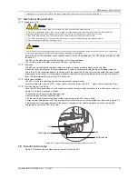
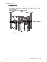
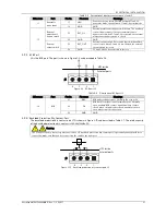
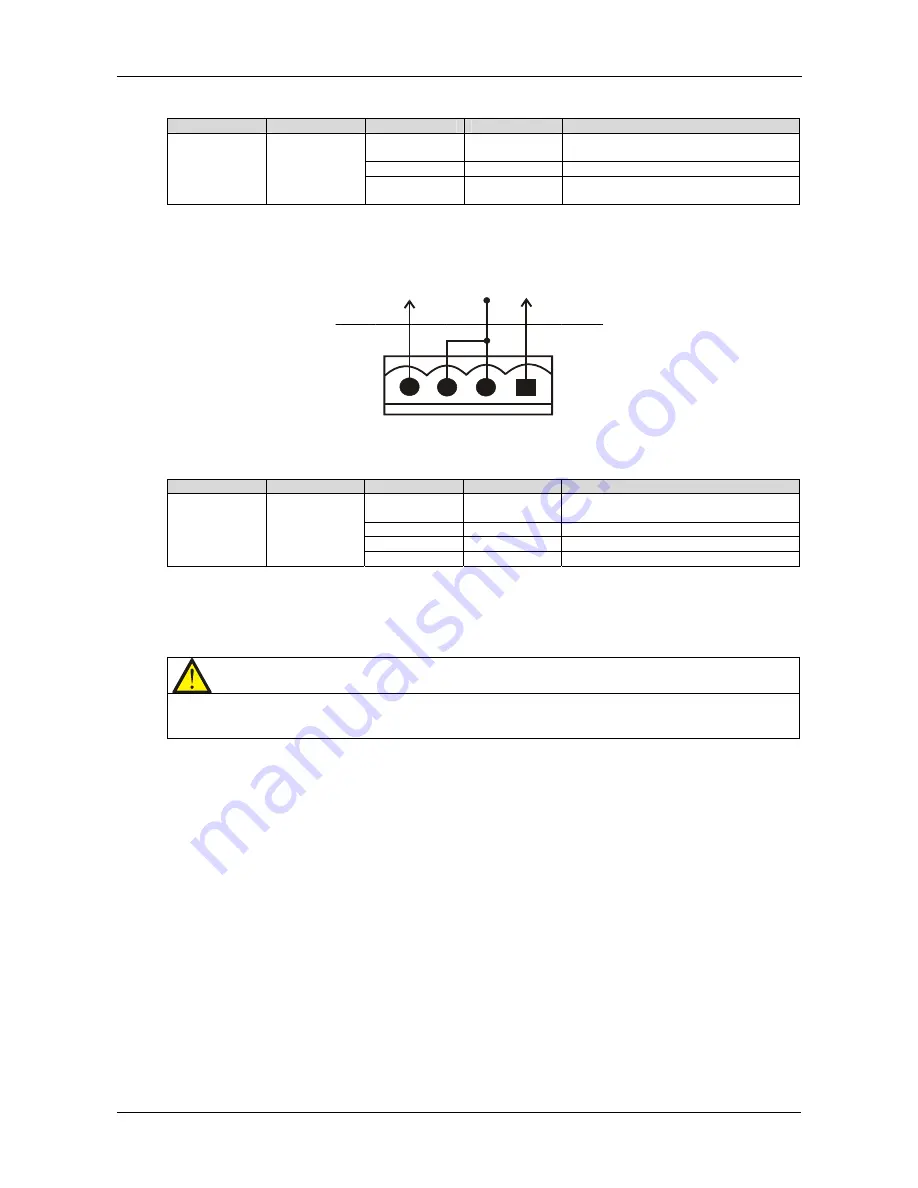
The remote EPO input port is J4. The port is shown in Figure 3-11 and described in Table 3-8.
+12V
1
2
3
4
J3
UPS inside
External ports
J4
Figure 3-11
Remote EPO input port J4
Table 3-8
Description of remote EPO input port J4
Silkscreen
Port
Pin No.
Pin name
Meanings
J4
Remote EPO
input
4.1 EPO_NC
EPO activated when opened to 4.2. Pins 4.1
and 4.2 have been shorted in factory
4.2
+12V
EPO activated when opened to 4.1
4.3
+12V
EPO activated when shorted to 4.4
4.4
EPO_NO
EPO activated when shorted to 4.3
EPO is triggered when pins 3 and 4 of J4 are shorted or pins 2 and 1 of J4 are opened.
If an external EPO facility is required, pins 1 and 2 or 3 and 4 of the REPO port are reserved for this function. The
external EPO facility is also connected to the normally open or normally closed remote EPO switch between these
two terminals using shielded cable. If this function is not used, pins 3 and 4 on the REPO input port must be open,
while pins 1 and 2 must be shorted.
Note
The UPS EPO action shuts down the rectifier, inverter and static bypass, but it does not disconnect the main input power
internally. To disconnect all power to the UPS, open the external power switch, bypass input switch, output switch and BCB
after activating the EPO.
3.2.6
RS232 Communication Port
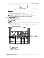
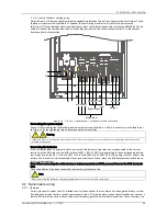
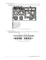
See Figure 3-7 for the location of the RS232 port. The RS232 port can be connected to an external computer in order
to monitor and set-up parameters.
The RS232 port provides serial data and is intended for use by authorized commissioning and service personnel
when commissioning and servicing the UPS.
3.2.7
USB Communication Port
The location of the USB port is shown in Figure 3-7.
The USB port can be used to connect the monitoring software.
To connect the communication cable, proceed as follows:
Connect one end of the USB communication cable to the USB port (see Figure 3-7) in the communication box, and
the other end to the USB port of the computer.
After connecting the pc to the USB port, install the USB driver on the installation disk.
Note: Do not connect the RS232 port and USB port to the computer at the same time as this could
compromise correct communication.
3.2.8
Parallel And LBS Communication Ports
See Figure 3-7 for the positions of these ports.
3.2.9
RS485 Communication Port
See Figure 3-7 for the position of this port.
See Table 3-9 for definition of the pins, and see Figure 3-12 for the cable connection diagram of the RS485
communication port.

