UPS OPERATION INTRODUCTION
46
User Manual 10H52246UM60 - Rev. 1 - 01/2017
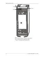
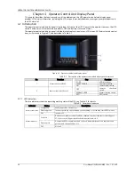
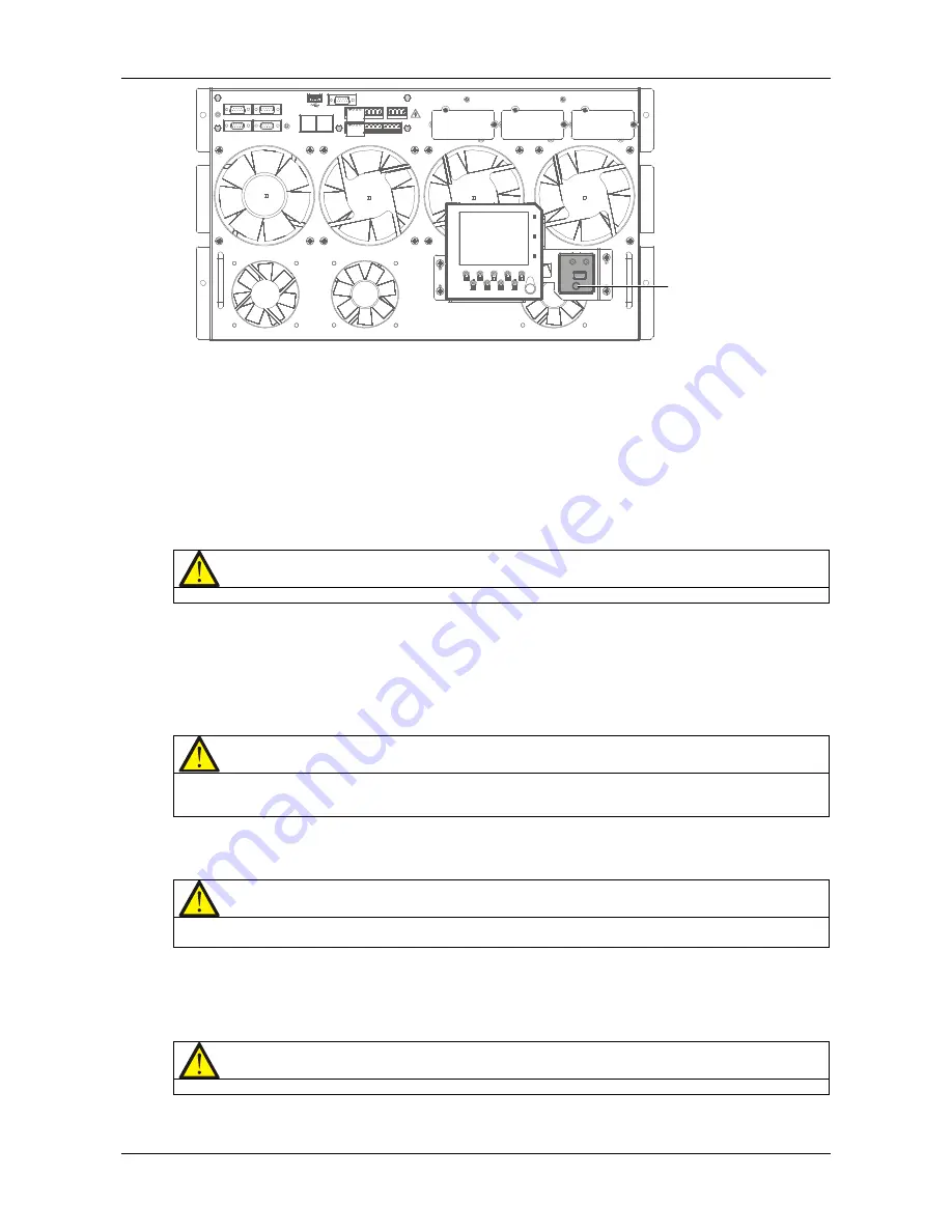
Battery cold start button
Figure 5-2
Battery cold start button
5.3
Procedures For Transfer Between Operation Modes
5.3.1
Transfer From Normal Mode To Battery Mode
Open the external rectifier input power switch to isolate the mains power and transfer the UPS to battery operating
mode. To transfer the UPS back to normal mode, wait for several seconds, and then close the external power switch
to re-connect the mains power to the UPS. 10 seconds later, the rectifier restarts automatically to feed power to the
load via the inverter.
5.3.2
Transfer From Normal Mode To Bypass Mode
Press the OFF key for two seconds, the inverter indicator (green) is extinguished, and the UPS transfers from normal
mode to bypass mode.
Note
In bypass mode, the load is directly fed by the mains power instead of the pure AC power from the inverter.
5.3.3
Transfer From Bypass Mode To Normal Mode
When the UPS is in bypass mode, press the ON key for two seconds, the inverter starts up, and the inverter indicator
(green) starts flashing until the inverter is operating normally, at this point the UPS is transferred from bypass mode
to normal mode.
5.3.4
Transfer From Normal Mode To Maintenance Mode
The following procedures will transfer the UPS from inverter output mode to the maintenance bypass mode.
Caution: power supply interruption risk to load
Before carrying out this procedure, read the information on the LCD to make sure that the bypass supply is normal and that
the inverter is synchronized with the bypass supply, in order to avoid risking a short interruption in the power supply to the
load.
1. Press the OFF key for at least two seconds. At this point, the inverter indicator (green) is extinguished,
accompanied by an audible alarm. The load transfers to the static bypass, and the inverter shuts down.
Note
Pressing the ALARM CLEAR key silences the audible alarm but the alarm message is displayed until the alarm condition is
rectified.
2. Close the maintenance bypass switch Q3 when the UPS is in single module mode.
3. At this point, the maintenance bypass is connected in parallel with the UPS static bypass.
4. The LCD displays 'Maint. sw. closed'.
5. Open the output switch Q5 and neutral line switch Q6.
this point, the load is powered directly by the maintenance bypass.
Caution
When the system is in maintenance bypass, the load is not protected against abnormal mains supply conditions.
6. Pressing the EPO button de-energizes the rectifier, inverter, static switch and battery, but does not affect the
maintenance bypass, which continues to power the load normally.

