UPS OPERATION INTRODUCTION
User Manual 10H52246UM60 - Rev. 1 - 01/2017
47
Note
When the system is in maintenance bypass, the load is fed directly by the mains power instead of the pure AC power from the
inverter.
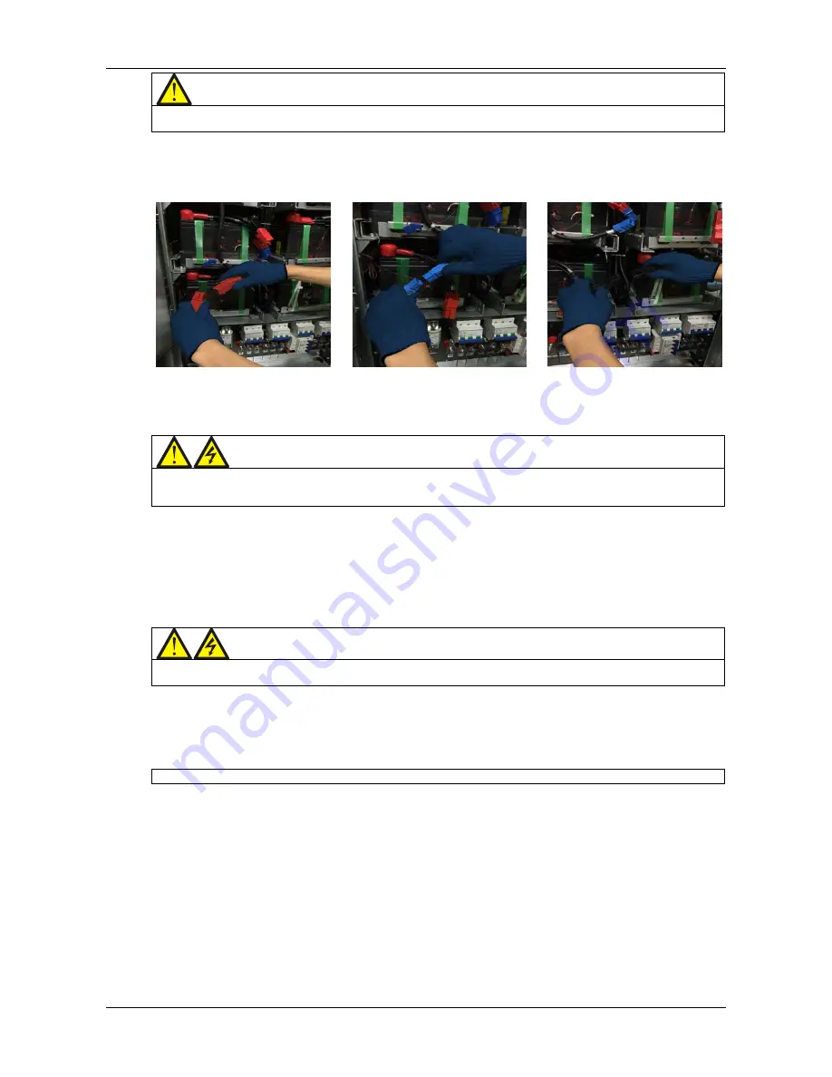
7. If the UPS has internal battery, use the special tool to open the battery compartment door, then disconnect the
three terminals 'BAT+' (W21, W11), 'BAT-' (W19, W08), and 'BAT N' (W20, W10), arc preventive safety gloves must
be worn when carrying out this operation, see Figure 5-3 for details. If the UPS is connected to an external
battery, open the corresponding external battery switch .
BAT + (Red)
BAT N (Blue)
BAT - (Black)
Figure 5-3 Photographs illustrating how to disconnect the internal terminals
8. Open the rectifier input switch QS1 and bypass input switch QS2.
At this point, all the internal UPS power supplies are disconnected and the LCD does not display any more.
Warning
1. If UPS maintenance is required, wait 10 minutes for the internal DC bus capacitors to discharge completely.
2. Hazardous voltages are present at some points on the UPS circuits, even when the rectifier input switch, bypass input
switch and battery switch are open. Therefore, UPS maintenance must be carried out by qualified personnel only.
5.3.5
Transfer From Maintenance Mode To Normal Mode
The following procedures will transfer the UPS from maintenance bypass supply mode to normal mode.
1. Open the front door, close the neutral line switch Q6.
2. Close the output switch Q5.
3. Close the bypass input switch Q2.
4. Once the LCD has started up, the Event menu window is displayed until the system confirms that the record
displays 'Bypass mode'.
Warning
Make sure that you close the bypass input switch before opening the maintenance bypass switch or the power supply to the
load will be interrupted.
5. Open the internal maintenance bypass switch Q3.
6. Close the rectifier input switch Q1, the alarm indicator (red) starts flashing.
7. Press the ON key for two seconds.
The inverter starts up, and the inverter indicator (green) starts flashing. Once the inverter is running normally, the
UPS is transferred from the bypass to inverter, and the inverter indicator (green) is illuminated (no longer flashing).
At this point, the load has transferred to UPS normal mode.
5.4
Battery Test Procedures
The battery test function is disabled by default. If you require this function, please contact your Vertiv customer
service engineer.
Battery test type and preconditions
1. There are two battery test modes to select from:
Battery maintenance test: verifies the integrity of the battery integrity; the battery is partially discharged
(20%) during this test
Battery capacity test: accurately determines the battery capacity; the battery is fully discharged during this
test (until the Battery low pre-warning alarm is activated)
2. The operator can perform the tests via the UPS control and display panel provided the following conditions are
satisfied:
The load must be greater than 5% of the rated UPS capacity and must be stable (battery maintenance test)

