BATTERY
58
User Manual 10H52246UM60 - Rev. 1 - 01/2017
External battery string
UPS
Battery
+
N
-
Communication
J4
GND
FB
DRV
BCB
UV
220Vdc
Auxiliary
X100
OUT-P
OUT-N
AUX1
AUX2
BCB control board
X103
X104
X105
X106
X101
X108
X102
GND1
AUX
DRV
X107
1
2
3
box
input
terminal
contactor
Note:
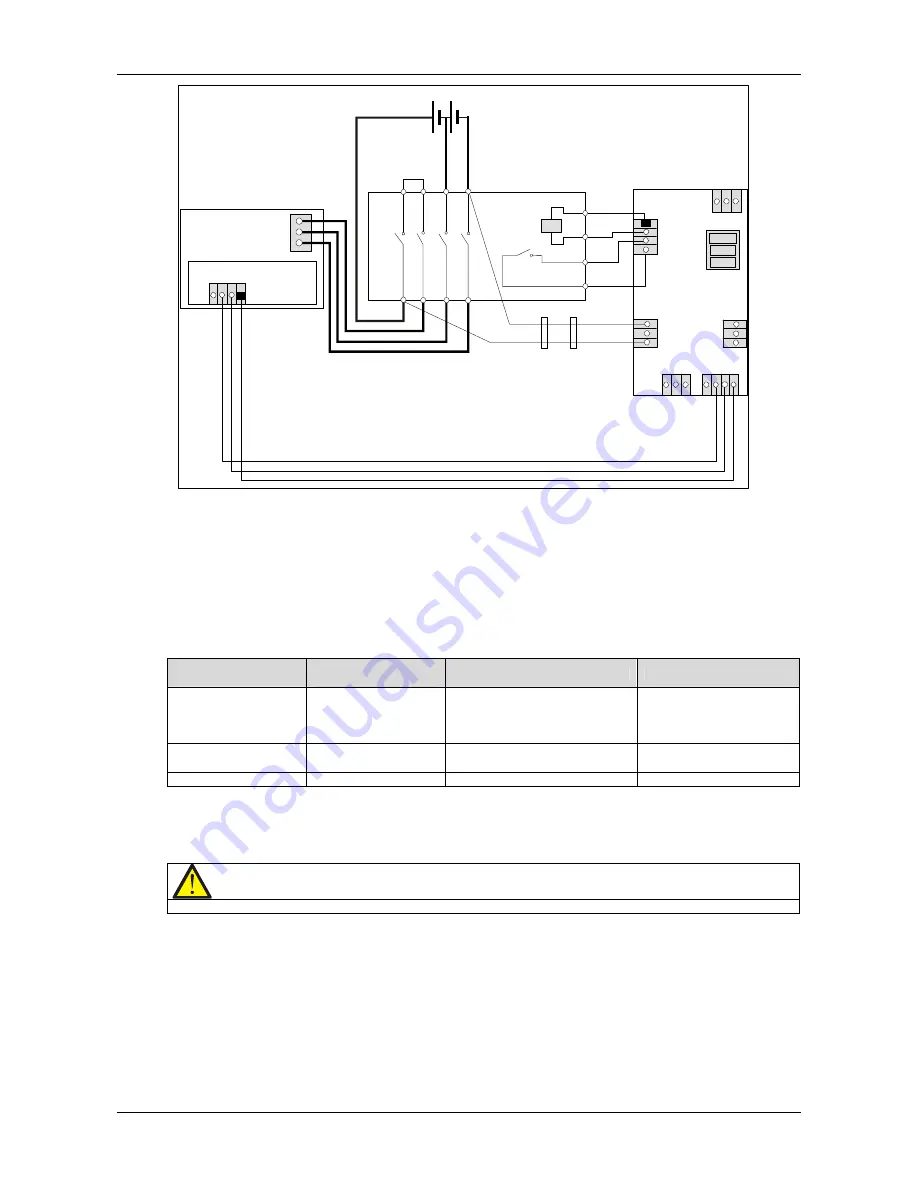
1. See Table 6-5 for definition of port X102.
2. X101-Hazardous Voltage: Do not conncet this port to the battery unless a permission given by the service engineer.
3. X103
~
X106 are used to connect temperature sensors from multiple battery cabinets.
4. X107 is used to set jumpers according to whether the UPS has been installed a battery cold button. If yes, jumpers 1, 2
setting is recommended; if not, jumpers 2, 3 setting is required.
Figure 6-4
BCB box connections
Table 6-5
Battery control port (X102)
BCB box port
Communication box
port (J4)
Meaning
Signal state
DRV
DRV
BCB trip control signal from UPS
Normal: high level, BCB
closed;
Abnormal: low level, BCB
open
IN (AUX)
FB (IN)
BCB auxiliary contact
(contact off = BCB off)
Normal: 0V, BCB closed;
Abnormal: open, BCB open
GND1
GND
Signal ground
GND1 to GND
Note: The cable connected to BCB port X102 must be routed separately from the power cable. It uses dual-insulated
shielded cable (the CSA is generally 0.5mm
2
~ 1mm
2
when the wiring distance is 25m ~ 50m length), and the two
ends of the shield must be connected to the enclosure securely. The separate safety earth must be connected
between the UPS and BCB box.
Caution
If the corresponding functions are not required, simply leave the corresponding ternimals unconnected.
6.10
BCB Reference Current And Connection
Table 6-6 indicates the recommended BCB rated current and battery maximum discharge current at full load. Refer
to Table 3B in IEC60950-1, and select the appropriate cable CSA according to local electrical regulations.


