PARALLEL SYSTEM AND LBS SYSTEM
62
User Manual 10H52246UM60 - Rev. 1 - 01/2017
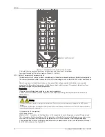
Note: Figure 7-3 illustrates two alternative EPO dry contact wiring diagrams, the top one is the Normally
Open type, and the bottom one is the Normally Closed type.
7.3
Parallel System Operating Procedures
Warning
If an RCD is installed on the UPS input line, the differential switch must only be used on the system bypass mains supply line.
At the moment of electrical connection, the current may not be separated immediately, which may cause the RCCB to trip.
The following procedures must be performed one step at a time, and each step must be completed before moving
on to the next one.
7.3.1
Startup Procedures In Normal Mode
These procedures are used to switch the UPS on starting from the fully powered-down state, which means that
neither the UPS nor the maintenance bypass switch have supplied power to the load before. Make sure the UPS has
been completely installed and commissioned by the engineer, and that external power supply switch is open.
Warning
1. These procedures result in mains voltage being applied to the UPS output terminals.
2. If any load equipment is connected to the UPS output terminals, check with the user that it is safe to apply power. If the load
is not ready to receive power, disconnect the downstream load switch, and position a warning label on the load connection
point.
Use the following procedures to switch on the UPS from a fully powered down condition.
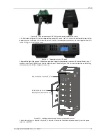
1. Confirm that all the external maintenance bypass switches are open. Open the front door of each UPS in turn and
ensure that the internal maintenance bypass switch Q3 is open and switch Q6 is closed on each unit, and that the
input cables and copper bars, and the parallel cables are connected securely.
Warning
To avoid being misinterpreted as fault conditions, all operations where it is necessary to open or close the maintenance bypass
switch must be concluded within three seconds.
2. Close the all the bypass input switches.
3. Close the bypass input switch QS2, rectifier input switch QS1 and all external output isolating switches (if any) on
each UPS in turn
At this point, the system is on, and the startup screen appears. Refer to 4.2.1
Start Screen
.
About 25 seconds later, confirm that the LCD indicates that the rectifier power supply and the bypass power supply
are within normal limits; if not, check whether the switches QS1 and QS2 are closed and the parallel cables of each
UPS are connected securely. At this point the rectifier starts up and the alarm indicator (red) is illuminated. At the
same time, the bypass static switch is closed. About 30 seconds later, the alarm indicator (red) starts flashing or is
extinguished (if the battery is connected), and the rectifier startup phase is complete. At this point the rectifier
startup phases are complete for all the UPS modules in the system.
4. Press and hold the ON key on each for two seconds. The inverters start up, and the inverter indicators (green) on
each UPS start flashing. After all the UPS inverter indicators are illuminated (no longer flashing), the parallel UPS
system starts supplying power to the load.
7.3.2
Maintenance Bypass Procedures
Warning
If the UPS system consists of more than 2 parallel UPS modules, and the load capacity exceeds the single module capacity, do
not use the internal maintenance bypass switch.
This operation will transfer the load transfer from the protected UPS power supply output so that it is connected
directly to the AC bypass input line.
Caution: power supply interruption risk to load
Before carrying out this procedure, read the information on the LCD to make sure that the bypass supply is normal and that
the inverter is synchronized with the bypass supply, in order to avoid risking a short interruption in the power supply to the
load.
1. Press and hold the OFF key on each UPS module in turn for two seconds. The inverter indicators are extinguished
and the buzzer alarms are activated. The load transfers to the static bypass, and the inverters shut down so that the
UPS system is operating bypass mode.
Note


