background image

Battery Installation

Vertiv

Large System, 3-Phase UPS Battery System Installation Manual

10

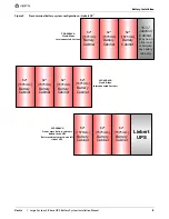
Figure 5

Top-terminal battery system configurations—Liebert NXL

250-400kVA

Stand-Alone

Interconnected Systems

55" battery cabinet must be 

on the right side of the 47" 

(1194mm) cabinets.

47"

(1194mm)

Battery

Cabinet

47"

(1194mm)

Battery

Cabinet

47"

(1194mm)

Battery

Cabinet

55"

(1397mm)

Battery

Cabinet

47"

(1194mm)

Battery

Cabinet

47"

(1194mm)

Battery

Cabinet

47"

(1194mm)

Battery

Cabinet

Liebert 

UPS

47"

(1194mm)

Battery

Cabinet

47"

(1194mm)

Battery

Cabinet

47"

(1194mm)

Battery

Cabinet

15-½"

Junction

Cabinet

(May be on 

either end 

or between 
any battery 

cabinets )

500-750kVA

Stand-Alone

Interconnected Systems

47"

(1194mm)

Battery

Cabinet

47"

(1194mm)

Battery

Cabinet

47"

(1194mm)

Battery

Cabinet

17-½"

Junction

Cabinet

(May be on 

either end 

or between 
any battery 

cabinets )

800-1100kVA

Stand-Alone

Connected Systems

250-750kVA

One or more battery cabinets bolted to the UPS

Battery cabinets may be on either side of a 

250-300kVA UPS and 400kVA 480V UPS. 

Battery cabinets must be on the left side of a 

500-750kVA UPS.

Battery cabinets must be on the left side of a 

400kVA 575/600V UPS.

Summary of Contents for Liebert NXL 1100

Page 1: ...l un I Jet _________ __ Liebert NXL https www uni jet com catalog istochniki besperebojnogo pitaniya on line ibp 100 kva liebert chloride nxl html...

Page 2: ...Liebert Large System 3 Phase UPS Battery System Installation Manual...

Page 3: ...ervices offers a complete range of startup services repair services preventive maintenance plans and service contracts For repair or maintenance service outside the 48 contiguous United States contact...

Page 4: ...mposition 6 2 0 BATTERY INSTALLATION 7 2 1 Safety 7 2 2 Layout 8 2 3 Cable Entry 15 2 4 Power Connection 15 2 4 1 Connected System 15 2 4 2 Connected or Stand Alone Arrangement 16 2 4 3 Grounding 16 2...

Page 5: ...7 Battery temperature sensor control connection 20 Figure 18 Outline drawing Liebert top terminal 47 1194mm wide battery cabinet 21 Figure 19 Main components Liebert top terminal 47 1194mm wide batter...

Page 6: ...iebert NXL 625 750kVA UPS to top terminal battery and attached junction cabinet point to point wiring 47 Figure 46 Terminal details Liebert NXL 625 750kVA UPS to top terminal battery and stand alone j...

Page 7: ...rt NXL terminal details UPS 625 750kVA to front terminal battery and attached junction cabinet point to point Interconnect wiring 45 Table 12 Liebert NXL terminal details UPS 625 750kVA to front termi...

Page 8: ...sulfuric acid can cause severe burns The following precautions must be observed when working on batteries Remove watches rings and other metal objects Use tools with insulated handles Wear rubber glov...

Page 9: ...be kept free of puddles of water excess moisture and debris Observe all precautions in the relevant operation and maintenance manual before as well as during all installation and maintenance procedure...

Page 10: ...life and capacity Typical battery manufacturer performance data are quoted for an operating temperature between 68 and 77 F 20 and 25 C Operating above this range will reduce the battery life while op...

Page 11: ...that any lifting equipment used to move the battery equipment has sufficient lifting capacity Battery system equipment can be handled by a forklift or similar equipment Because the weight distributio...

Page 12: ...nal battery cabinet standard width Figure 2 Shipping bolts Top terminal battery cabinet reduced width Outer doors not shown Shipping Bolts Shipping Bolts Shipping Bolts Shipping Bolts Shipping Bolts S...

Page 13: ...ervice access Clearance around the front of the equipment should be sufficient to enable free passage of personnel with the doors fully opened 1 4 3 Raised Floor Mounting If the equipment is to be pla...

Page 14: ...ck or burn from high short circuit currents When connected in a string the voltage will exceed 400VDC This voltage is potentially lethal Always observe high voltage precautions Eye protection must be...

Page 15: ...front terminal battery cabinets Figure 3 Top terminal battery system configurations Liebert eXL 47 1194mm Battery Cabinet 47 1194mm Battery Cabinet 47 1194mm Battery Cabinet 15 Junction Cabinet May b...

Page 16: ...47 1194mm Battery Cabinet 15 Junction Cabinet May be on either end or between any battery cabinets 225 400kVA Stand Alone Interconnected Systems 47 1194mm Battery Cabinet 47 1194mm Battery Cabinet 47...

Page 17: ...UPS 47 1194mm Battery Cabinet 47 1194mm Battery Cabinet 47 1194mm Battery Cabinet 15 Junction Cabinet May be on either end or between any battery cabinets 500 750kVA Stand Alone Interconnected System...

Page 18: ...Figure 7 Top terminal battery system configuration Battery cabinets not attached to UPS or each other Liebert eXL Liebert NX and Liebert NXL 55 1397mm Battery Cabinet 55 1397mm Battery Cabinet 55 1397...

Page 19: ...een any battery cabinets 625 750kVA Stand Alone Interconnected Systems 625 1200kVA One or more battery cabinets bolted to the UPS Battery cabinets must be on the left side of the UPS 62 1575mm Battery...

Page 20: ...binet 62 1575mm Battery Cabinet 15 Junction Cabinet May be on either end or between any battery cabinets 225 400kVA Stand Alone Interconnected Systems 62 1575mm Battery Cabinet 62 1575mm Battery Cabin...

Page 21: ...62 1575mm Battery Cabinet 62 1575mm Battery Cabinet 15 Junction Cabinet May be on either end or between any battery cabinets 500 750kVA Stand Alone Interconnected Systems 62 1575mm Battery Cabinet 62...

Page 22: ...tems and Figures 8 through 12 for front terminal battery systems NOTICE Risk of improper cable connections Can cause equipment damage Cables between the batteries and the UPS should be run in matched...

Page 23: ...hardware will be supplied See Figure 34 for location of cabinet to cabinet grounding For cabinets ordered as detached or stand alone customer must supply the cables and hardware See the terminal deta...

Page 24: ...um Voltage Maximum Current TB1154 1 CAN 24V 24VDC 2A 2 CAN Common 3 CANbus High 4 CANbus Low 1 To prevent signal interference low voltage 48V and low current 5A cable groups should be run in separate...

Page 25: ...N multi module unit with static bypass Control LCD Main Input Circuit Breaker CB1 optional Backfeed Circuit Breaker BFB External Communication Panel See Detail A X3 XS3 X6 XT1 2 XT3 8 X19A X20 X9 XT4...

Page 26: ...NXL Figure 16 shows the contacts used to communicate between the UPS module and battery cabinets or module battery disconnects Figure 16 Wiring external interface board in Liebert NXL to battery inte...

Page 27: ...ransformer The transformer is powered from the output of the UPS the battery cabinet is supplying see Figure 52 The Alber monitoring system consists of a Control Module and a Battery Module see Figure...

Page 28: ...DE ISOMETRIC VIEW 1 24 610mm minimum clearance above the unit is required for air exhaust 2 Keep cabinet within 15 degrees of vertical 3 Top and bottom cable entry is available through removable acces...

Page 29: ...ltage Control Cable Trough TOP VIEW BDSUi Control Module Optional BDSUi Battery Module Optional Batteries FRONT VIEW Doors and Panels Not Shown FRONT VIEW FRONT Battery Interface Board BIB Battery Bre...

Page 30: ...tery cabinet Positive Terminal Bus Negative Terminal Bus FRONT TOP VIEW TOP VIEW Door Open RIGHT SIDE VIEW 57 1 1451mm NOTES 1 Top and bottom cable entry available through removable access plates 2 Co...

Page 31: ...above the unit is required for air exhaust 2 Keep cabinet within 15 degrees of vertical 3 Top and bottom cable entry is available through removable access plates 4 Control wiring and power wiring mus...

Page 32: ...age Control Cable Trough TOP Front BDSUi Control Module Optional BDSUi Battery Module Optional Battery Service Tray Battery Service Tray Supports Batteries Typical View FRONT VIEW OF INNER DOORS FRONT...

Page 33: ...79mm Outside Frame 5 127mm Outside Frame 5 7 144mm 3 76mm 12 305mm 8 9 226mm Low Voltage High Voltage FRONT CONDUIT DETAIL A Top Conduit Plate FRONT FRONT CONDUIT DETAIL B Bottom Conduit Plate Positi...

Page 34: ...Split 1 24 610mm minimum clearance above the unit is required for air exhaust 2 Keep cabinet within 15 degrees of vertical 3 Top and bottom cable entry is available through removable access plates 4 C...

Page 35: ...able Trough Low Voltage Control Cable Trough TOP BDSUi Control Module Optional BDSUi Battery Module Optional Batteries Typical View FRONT VIEW Doors and Panels Not Shown FRONT VIEW Battery Interface B...

Page 36: ...To Panel 0 9 23mm 9 4 240mm 21 2 538mm 10 254mm Low Voltage Cable Entry High Voltage Cable Entry CONDUIT DETAIL A Top Conduit Plate FRONT FRONT FRONT CONDUIT DETAIL B Bottom Conduit Plate POSITIVE NEG...

Page 37: ...these wires Install snap bushing in corner post before routing these wires Route two supplied wires W17 from Jar 15 to Jar 16 Note Install bushing first Route two supplied wires W16 from Jar 1 to BCB...

Page 38: ...ide panels 5 The depth dimension includes the front door and rear panel 13 7 348 Negative Bus Ground Bus Positive Bus Ground Bus Negative Bus Positive Bus 9 0 228 8 7 221 7 4 189 56 14 Typ 56 14 Typ 5...

Page 39: ...us Bottom Negative Bus Bottom Ground Bus 1 75 44mm Typ 0 56 14mm Typ 4 4 112mm 49 1 1248mm 37 3 948mm 26 661mm 1 75 44mm Typ 2 51mm Typ 2 51mm Typ 7 178mm 11 4 290mm 1 75 44mm Typ 0 56 14mm Typ 0 56 1...

Page 40: ...tions Brackets must remain attached to the frame until the unit is being placed in its final installation location The final installation will always require the unit to be bolted to another Liebert p...

Page 41: ...gs Vertiv Large System 3 Phase UPS Battery System Installation Manual 34 Figure 31 17 junction cabinet junction cabinet REAR 553636 Rev 0 FRONT FRONT VIEW 41 04 1042 5mm 9 59 243 5mm Center of Gravity...

Page 42: ...1154 2 GND Black 3 TB1154 3CANH White 4 TB1154 4CANL Black 1 2 3 4 5 7 6 5 4 3 2 1 1 2 3 4 3 2 1 1 TB1154 1 24V Red 2 TB1154 2 GND Black 3 TB1154 3 CANH White 4 TB1154 4 CANL Black TB1154 TB1158 Batte...

Page 43: ...de if cabinets ordered as stand alone Reference of corner post of connected cabinets Cabinet to Cabinet Bolting Instructions NOTES 1 Apply ground strap hardware to specified locations 2 Torque Values...

Page 44: ...ower RH Mount Stand Alone A2 UPS DC Busbar Battery Cabinet DC Busbar Positive Power Left Mount B2 UPS DC Busbar Battery Cabinet DC Busbar Negative Power Left Mount C UPS Ground Battery Cabinet Ground...

Page 45: ...alone junction cabinet Table 4 Liebert top terminal standard width battery cabinet interconnect wiring to Liebert junction cabinet Run From To Conductors A Battery Cabinet Negative Bus Junction Negat...

Page 46: ...ve DC Power RH Mount Stand Alone A2 UPS DC Positive Busbar Battery Cabinet Positive Bus Positive DC Power Left Mount B2 UPS DC Negative Busbar Battery Cabinet Negative Bus Negative DC Power Left Mount...

Page 47: ...Cabinet Negative Bus Junction Negative Bus Negative DC Power B Battery Cabinet Positive Bus Junction Positive Bus Positive DC Power C Battery Cabinet Ground Junction Ground Ground D Junction Positive...

Page 48: ...ive Bus Positive DC Power LH Mount A2 Battery Cabinet Negative Bus Junction Negative Bus Negative DC Power RH Mount B2 Battery Cabinet Positive Bus Junction Positive Bus Positive DC Power RH Mount D J...

Page 49: ...s Junction Negative Bus Negative DC Power B Battery Cabinet Positive Bus Junction Positive Bus Positive DC Power C Battery Cabinet Ground Junction Ground Ground D Junction Positive Bus UPS Cabinet Pos...

Page 50: ...n From To Conductors A UPS Positive Bus Battery Cabinet Positive Bus Positive DC Power B UPS Negative Bus Battery Cabinet Negative Bus Negative DC Power D UPS External Interface Board EIB Battery Cabi...

Page 51: ...Run From To Conductor A UPS Positive Bus Battery Cabinet Positive Bus Positive DC Power B UPS Negative Bus Battery Cabinet Negative Bus Negative DC Power D UPS External Interface Board EIB Battery Ca...

Page 52: ...RH Mount B2 Battery Cabinet Positive Bus Junction Positive Bus Positive DC Power RH Mount D Junction Positive Bus UPS Cabinet Positive Bus Positive DC Power E Junction Negative Bus UPS Cabinet Negativ...

Page 53: ...Bus Negative DC Power B Battery Cabinet Positive Bus Junction Positive Bus Positive DC Power C Battery Cabinet Ground Junction Ground Ground D Junction Positive Bus UPS Cabinet Positive Bus Positive D...

Page 54: ...ve Bus Positive DC Power LH Mount A2 Battery Cabinet Negative Bus Junction Negative Bus Negative DC Power RH Mount B2 Battery Cabinet Positive Bus Junction Positive Bus Positive DC Power RH Mount D Ju...

Page 55: ...Bus Junction Negative Bus Negative DC Power B Battery Cabinet Positive Bus Junction Positive Bus Positive DC Power C Battery Cabinet Ground Junction Ground Ground D Junction Positive Bus UPS Cabinet...

Page 56: ...iring Run From To Conductor A UPS Positive Bus Battery Cabinet Positive Bus Positive DC Power B UPS Negative Bus Battery Cabinet Negative Bus Negative DC Power D UPS External Interface Board EIB Batte...

Page 57: ...tery Cabinet Positive Bus Junction Positive Bus Positive DC Power RH Mount D Junction Positive Bus UPS Cabinet Positive Bus Positive DC Power E Junction Negative Bus UPS Cabinet Negative Bus Negative...

Page 58: ...ower B Battery Cabinet Positive Bus Junction Positive Bus Positive DC Power C Battery Cabinet Ground Junction Ground Ground D Junction Positive Bus UPS Cabinet Positive Bus Positive DC Power E Junctio...

Page 59: ...s Vertiv Large System 3 Phase UPS Battery System Installation Manual 52 Figure 50 Typical Alber battery monitoring connections Alber Control Module Alber Battery Module Alber Power Transformer Input F...

Page 60: ...e X1 and X2 Item 20 Item 11 Item 12 Secure the ground wire under the transformer s foot with Items 30 31 and 32 Primary Side Multiple Taps BOTTOM TERMINALS TOP TERMINALS Fuses supplied installed in ca...

Page 61: ...ensor 9 9 4 5 3 8 BATTERY STRING LOAD CHARGER or Resistive load voltage sense and intertier sense connections to the battery depend on the battery configuration Red Dot To UPS Protected 120VAC 2 UXBM...

Page 62: ...EAR OF TRAY FRONT OF TRAY REAR OF TRAY FRONT OF TRAY REAR OF TRAY FRONT OF TRAY REAR OF TRAY FRONT OF TRAY REAR OF TRAY FRONT OF TRAY REAR OF TRAY FRONT OF TRAY JAR 2 JAR 3 JAR 4 JAR 40 JAR 39 JAR 38...

Page 63: ...nfiguration FRONT JAR 18 JAR 16 JAR 17 JAR 3 JAR 1 JAR 15 JAR 13 JAR 14 JAR 6 JAR 4 JAR 9 JAR 7 JAR 12 JAR 10 CABINET A CABINET B 30 29 28 27 26 25 24 23 22 21 20 19 18 17 16 15 14 13 12 11 10 9 8 7 6...

Page 64: ...Installation Manual 57 Figure 55 Busbar connection between battery cabinet and attached junction cabinet Left Side Busbar Connections Right Side Busbar Connections This connection is the same for top...

Page 65: ...nclosure IP 20 with and without front door open Minimum Clearance Top 24 610mm Minimum Clearance Back 0 Minimum Clearance Sides 0 Cable Entrance Top or Bottom Standards Conformities UL 1778 CSA 22 2 1...

Page 66: ...learance Back 0 Minimum clearance Sides 0 Location of cable entrance Top or Bottom Standards and Conformities UL 1778 CSA 22 2 107 3 FCC Part 15 Class A ISTA Procedure 1H WEEE IBC 2012 CBC 2010 Enviro...

Page 67: ...5585 2533 700AT 1200AF Enersys PX 12HX300 3525 1599 350AT 600AF 65 7 3 RX 12HX330 3965 1798 400AT 600AF UX 12HX400 4375 1984 450AT 600AF WX 12HX505 5295 2402 600AT 600AF XX 12HX540 5465 2479 600AT 60...

Page 68: ...54868BE 60156 60256 300kcmil 54914BE 54870BE 60162 60262 350kcmil 54915BE 54872BE 60165 60267 400kcmil 54916BE 54874BE 60168 60269 500kcmil 54918BE 54876BE 60171 60273 600kcmil 54920BE 54878BE 60176 6...

Page 69: ...Specifications Vertiv Large System 3 Phase UPS Battery System Installation Manual 62 NOTES...

Page 70: ...Specifications Vertiv Large System 3 Phase UPS Battery System Installation Manual 63...

Page 71: ...Specifications Vertiv Large System 3 Phase UPS Battery System Installation Manual 64...

Page 72: ...800 543 2378 Outside North America 614 841 6598 LOCATIONS United States 1050 Dearborn Drive P O Box 29186 Columbus OH 43229 Europe Via Leonardo Da Vinci 8 Zona Industriale Tognana 35028 Piove Di Sacco...

Page 73: ...es and logos referred to are trade names trademarks or registered trademarks of their respective owners While every precaution has been taken to ensure accuracy and completeness herein Vertiv Co assum...

Reviews: