Installation Drawings
Vertiv
|
Large System, 3-Phase UPS Battery System Installation Manual
37
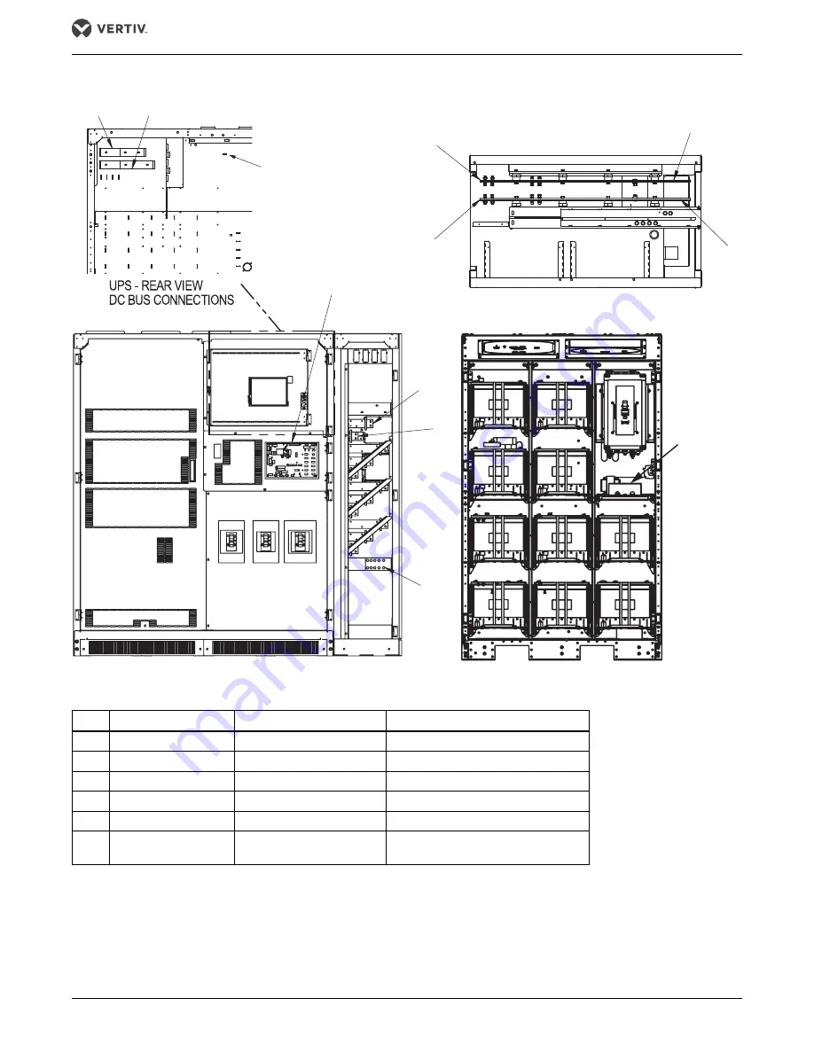
Figure 35
Top-terminal, standard width battery cabinet interconnection wiring to 250-400kVA UPS
Table 3
Top-terminal battery cabinet interconnection wiring to 250-400kVA UPS
Run
From
To
Conductors
A1
UPS - DC+ Busbar
Battery Cabinet - DC+ Busbar
Positive Power - RH Mount/Stand Alone
B1
UPS - DC- Busbar
Battery Cabinet - DC- Busbar
Negative Power - RH Mount/Stand Alone
A2
UPS - DC+ Busbar
Battery Cabinet - DC+ Busbar
Positive Power - Left Mount
B2
UPS - DC- Busbar
Battery Cabinet - DC- Busbar
Negative Power - Left Mount
C *
UPS - Ground
Battery Cabinet - Ground
Ground
D
UPS - External Interface
Board (EIB)
Battery Cabinet - Battery
Interface Board (BIB)
CAN Control Cables
* This is used only for detached cabinets. If the cabinets are attached, use the grounding shown in
.
B2
A2
B1
B1
A1
A1
For left -mounted
installations, the DC
cables will be routed
along the interior rear
of the UPS. The cables
can be supported using
lances in the UPS
sheet metal.
A2
B2
D
D
C
UPS
BATTERY CABINET
Summary of Contents for Liebert NXL 1100
Page 2: ...Liebert Large System 3 Phase UPS Battery System Installation Manual...
Page 69: ...Specifications Vertiv Large System 3 Phase UPS Battery System Installation Manual 62 NOTES...
Page 70: ...Specifications Vertiv Large System 3 Phase UPS Battery System Installation Manual 63...
Page 71: ...Specifications Vertiv Large System 3 Phase UPS Battery System Installation Manual 64...


