VertivCo.com
|
Vertiv Headquarters,
1050 Dearborn Drive, Columbus, OH, 43085, USA
© 2017 Vertiv Co. All rights reserved. Vertiv and the Vertiv logo are trademarks or registered trademarks of Vertiv Co. All other names and logos referred to are trade names, trademarks or
registered trademarks of their respective owners. While every precaution has been taken to ensure accuracy and completeness herein, Vertiv Co. assumes no responsibility, and disclaims all
liability, for damages resulting from use of this information or for any errors or omissions. Specifications are subject to change without notice.
590-1640-501A/SL-20861_REV4
2
vertiv™ MPH2™ rack Pdu
Quick Installation Guide
MPH2 Rack PDU Setup
NOTE:
It is recommended that all devices
powered through the MPH2 rack PDU
be turned off and unplugged from input
power sources.
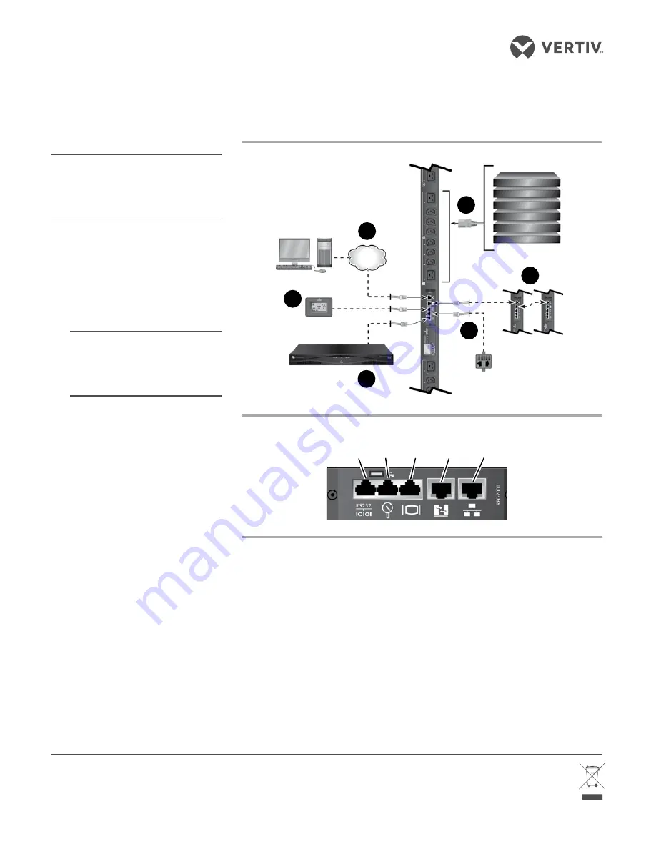
1. Connecting to a network
Connect an Ethernet cable
from your network to the RPC2
Communications Module’s
Network port.
2. Connect Devices’ Power
Cords
NOTE:
Record where each powered
device is connected using the
branch and receptacle IDs on the
MPH2 rack PDU for reference.
Connect the devices’ input power
supply cables to the MPH2 rack
PDU’s receptacles.
3. Creating a Rack PDU Array™
Use an Ethernet cable to connect
the Link port of the first MPH2 rack
PDU to the Network port of the
second MPH2 rack PDU; repeat for
up to two more MPH2 rack PDUs.
4. Connecting an SN sensor
Use an RJ45 compatible cable
to connect an SN sensor to
the Sensor port of the RPC2
Communications Module.
5. Connecting a console server
Use an RJ45 compatible cable to
connect a serial console server
to the Serial port of the RPC2
Communications Module.
6. Connecting a Basic Display
Module
Use an RJ45 compatible cable to
connect an optional Basic Display
Module (BDM) to the Display port
of the RPC2 Communications
Module.
7. Turning on the MPH2 rack
PDU
Ensure all circuit breakers on the
unit are in the Off position. Connect
input power to the MPH2 rack PDU.
Press the circuit breaker switches
into the On position. Verify voltage
on the LCD and that the LEDs are
illuminated. Connect each device’s
input power supply cable and verify
the current draw on the LCD.
8. Viewing IP address, MAC
address and Firmware
version
Use the arrow keys under the LCD
of the MPH2 rack PDU to highlight
the Information icon, then press
the select key, which is located
between the arrow keys. Use an
arrow key to highlight the Network
icon and press the select key again.
The LCD displays the IP address,
MAC address and RPC2 module
firmware version.
Serial
Port
RPC2 Communications Module Ports
MPH2 Rack PDU Configuration
(Vertical Model Shown)
�
Network
Basic Display Module
Console Server
or Switch
Sensor
Additional PDUs
Powered Devices
2
3
4
5
6
Sensor
Port
Display
Port
Link
Port
Network
Port


