background image


Vertiv


|


NetSure™ 2100 Series -48 VDC Power System Installation Manual (IM582138000)


|


Rev. C 

11 

CUSTOMER DOCUMENTATION PACKAGE 

This document (IM582138000) provides 

Installation Instructions

 for the NetSure™ 2100 SERIES -48 VDC Power 

System:  Model 2100, Spec. No. 582138000. 

The complete Customer Documentation Package consists of… 

Document Number 

Document Description 

How Provided 

IM582138000 

Power System Installation 

Instructions 

Printed Manual and PDF File 

UM1M831ANA 

Mini Control Unit User 

Instructions 

Printed Manual and PDF File 

(per configuration file loaded into 

controller) 

Mini Control Unit Configuration 

Drawing (C-drawing) 

Printed Document and PDF File 

UM582138000 

Power System User Instructions 

PDF files are provided on a 

supplied USB drive. 
 
See also Note 1. 

SAG582138000 

Power System “System 

Application Guide” 

UM1R481000e3 

Rectifier Instructions 

Section 4154 

Contact Information Page 

SD582138000 

Power System Schematic 

Diagram 

T582138000 

Power System Wiring Diagram 

Note 1:

  Also provided on the USB drive is a controller configuration drawing and the controller configuration 

files loaded into the controller as shipped. 

For factory settings of all configurable controller parameters, refer to the controller configuration drawing 
(C-drawing) supplied with your power system. 


INSTALLATION ACCEPTANCE CHECKLIST 

Provided in this section is an Installation Acceptance Checklist.  This checklist helps ensure proper installation 
and initial operation of the system.  As the procedures presented in this document are completed, check the 
appropriate box on this list.  If the procedure is not required to be performed for your installation site, also 
check the box in this list to indicate that the procedure was read.  When installation is done, ensure that each 
block in this list has been checked.  Some of these procedures may have been factory performed for you. 


NOTE!  

The system is not powered up until the end of this checklist. 


NOTE!  

Some of these procedures may have been performed at the factory for you. 


Summary of Contents for NetSure 2100 Series

Page 1: ...NetSure 2100 Series 48 VDC Power System Installation Manual IM582138000 Revision C Specification Number 582138000 Model Number 2100 ...

Page 2: ... the correct methods tools and materials to be used in performing procedures not specifically described in this document This document may contain confidential and or proprietary information of Vertiv Group Corp and its receipt or possession does not convey any right to reproduce disclose its contents or to manufacture or sell anything that it may describe Reproduction disclosure or use without sp...

Page 3: ...ring the System to a Wall with Wall Bracket Kit P N 541285 if furnished 19 Installing a List 93 94 Battery Tray and Optional Battery Tray Circuit Breaker 22 Battery Tray Installation 22 Optional Battery Disconnect Circuit Breaker Installation 30 Installing Circuit Breakers and Fuses 31 Installing GMT Load Distribution Fuses List AA BA BB CA 31 Installing Bullet Nose Type Load Distribution Circuit ...

Page 4: ...t Breaker Alarm Connections to Battery Disconnect Circuit Breakers on Battery Cabinets 54 Mini Control Unit Ethernet Connection if required 57 Mini Control Unit Second Ethernet Port Connection if Optional External IB4 Kit P N 559239 Furnished 58 General 58 Default IB4 Ethernet Port Parameters 58 Load Distribution Wiring Input Battery Wiring and CO Ground Wiring 60 Load Distribution Wiring Input Ba...

Page 5: ...on Manual IM582138000 Rev C 5 Configuring the System 74 Mini Control Unit 74 Mini Control Unit Controller Initialization 74 Setting the Mini Control Unit as Required for Your Application 76 Checking System Operation 79 Checking System Status 85 Final Steps 85 ...

Page 6: ... if not avoided ANSI OSHA This admonition is not used for situations that pose a risk only to equipment data or service even if such use appears to be permitted in some of the applicable standards OSHA ALERT Alerts the reader to an action that must be avoided in order to protect equipment software data or service ISO ALERT Alerts the reader to an action that must be performed in order to prevent e...

Page 7: ... operates from AC input voltage capable of producing fatal electrical shock AC input power must be completely disconnected from the branch circuits wiring used to provide power to the system before any AC electrical connections are made Follow local lockout tagout procedures to ensure upstream branch circuit breakers remain de energized during installation DO NOT apply AC input power to the system...

Page 8: ...njury from accidental electrical arcs Use certified and well maintained insulated tools Use double insulated tools appropriately rated for the work to be performed Ensure that wrenches with more than one working end have only one end exposed Do not lay tools or metal parts on top of batteries Verify that no current will flow when the battery is connected or disconnected by opening battery disconne...

Page 9: ...ork Permits as required by the local authority per NFPA 70E Standard for Electrical Safety in the Workplace Hazardous Voltage DANGER HAZARD OF ELECTRICAL SHOCK More than one disconnect may be required to de energize the system before servicing Handling Equipment Containing Static Sensitive Components ALERT Installation or removal of equipment containing static sensitive components requires careful...

Page 10: ...ernal resistor is necessary Read and follow wrist strap manufacturer s instructions outlining use of a specific wrist strap 3 Do not touch traces or components on equipment containing static sensitive components Handle equipment containing static sensitive components only by the edges that do not have connector pads 4 After removing equipment containing static sensitive components place the equipm...

Page 11: ...ower System Schematic Diagram T582138000 Power System Wiring Diagram Note 1 Also provided on the USB drive is a controller configuration drawing and the controller configuration files loaded into the controller as shipped For factory settings of all configurable controller parameters refer to the controller configuration drawing C drawing supplied with your power system INSTALLATION ACCEPTANCE CHE...

Page 12: ...Making Electrical Connections Relay Rack Cabinet Frame Grounding Connection Made System Shelf Frame Grounding Connection Made Central Office Ground Connection Made Rectifier AC Input and AC Input Equipment Grounding Connections Made External Alarm Reference Monitoring and Control Connections Made Mini Control Unit Ethernet Port Connection Made Mini Control Unit Second Ethernet Port Connection Made...

Page 13: ...o crafts persons only This product is intended for installation in network telecommunication facilities CO vault hut or other environmentally controlled electronic equipment enclosure This product is intended for connection to the common bonding network in a network telecommunication facility CO vault hut or other environmentally controlled electronic equipment enclosure The DC return connection t...

Page 14: ...re more clearance The system may also be mounted horizontally or vertically Vertical mounting can be with the distribution located at the top of the unit orientation or at the bottom of the unit orientation Securing the Relay Rack to the Floor if furnished Secure the relay rack to the floor per site requirements Refer to General Requirements on page 13 Ventilation Requirements Refer to General Req...

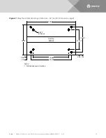
Page 15: ...4 2 56 0 875 Dia 8 Places Masked for Frame Ground Lug 0 281 Dia Holes on 0 625 Centers Top of Rack 2 Places 22 500 24 750 1 125 15 000 17 500 20 125 25 000 2 437 3 750 9 871 12 531 15 031 1 250 2 580 2 00 1 00 1 00 2 00 2 00 2 00 5 00 0 437 Dia 12 Places Masked for Frame Ground Lug 0 281 Dia Holes on 0 625 Centers Top of Rack 2 Places 0 875 Dia 8 Places Masked for Frame Ground Lug 0 281 Dia Holes ...

Page 16: ...em Installation Manual IM582138000 Rev C 16 Figure 1 Relay Rack Floor Mounting Dimensions 23 cont d from previous page 19 685 25 80 15 000 1 50 2 83 18 00 0 875 8 Places Part No 562353 12 340 22 310 3 06 1 74 Notes 1 All dimensions are in inches ...

Page 17: ...sked for Frame Ground Lug 0 281 Dia Holes on 0 625 Centers Top of Rack 2 Places Masked for Frame Ground Lug 0 281 Dia Holes on 0 625 Centers Top of Rack 2 Places 14 13 16 75 21 00 2 13 3 44 9 38 12 03 15 00 1 49 2 81 0 875 Dia 8 Places Notes 1 All dimensions are in inches Masked for Frame Ground Lug 0 334 Dia Holes on 0 625 Centers Top of Rack 2 Places Part No 563922 15 69 18 31 21 80 1 76 3 07 12...

Page 18: ...e system 2 Position the system in the relay rack or cabinet equipment rack 3 Secure the system to the relay rack or cabinet equipment rack using hardware as shown in Figure 3 see Figure 3 for recommended torque Use grounding washers as indicated in Figure 3 NOTE Install orient the ground washers so the teeth dig into the mounting angles for a secure ground connection NOTE Compliance with Telcordia...

Page 19: ...asteners for securing the system to a wall or other vertical surface Ensure that the wall and fastening technique are suitable for supporting the weight of the system Refer to System Application Guide SAG582138000 for system weight and additional dimensions 2 Select either the vertical mount or horizontal mount brackets as required for your application Attach the brackets to the system mounting an...

Page 20: ...90 18 80 13 19 19 53 Notes 1 All dimensions are in inches unless otherwise specified 2 Installer to furnish hardware for fastening brackets to wall Front Horizontal Wall Mounting Bracket 2 Installer to furnish hardware for fastening brackets to wall Fasten kit brackets to shelf angles with kit furnished fasteners Fasten kit brackets to shelf angles with kit furnished fasteners Installer to furnish...

Page 21: ...g brackets to wall 18 31 1 15 75 2 68 19 80 Wall Mount Drill Guide Not to scale 1 15 18 3 0 277 Dia Clearance Hole in Bracket for Wall Fastener Front Rear Vertical Wall Mounting Bracket 2 Fasten kit brackets to shelf angles with kit furnished fasteners Fasten kit brackets to shelf angles with kit furnished fasteners Front Installer to furnish hardware for fastening brackets to wall Installer to fu...

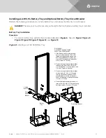
Page 22: ...y Rear Angle Bracket Rear Angle Bracket Cabling Bracket Front Rear 1 Slide battery tray into relay rack and secure to relay rack with 12 24 x 3 4 thread forming hex head screws and 10 12 ground washers 1 place per side or 12 flat washers 3 places per side Torque to 70 in lbs 2 Secure rear angle brackets both sides to battery tray with 1 4 20 x 3 4 bolts 1 4 flat washers 1 4 lock washers and 1 4 nu...

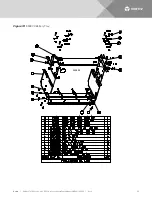
Page 23: ...Vertiv NetSure 2100 Series 48 VDC Power System Installation Manual IM582138000 Rev C 23 Figure 7 559806 Battery Tray 559806 ...

Page 24: ...Vertiv NetSure 2100 Series 48 VDC Power System Installation Manual IM582138000 Rev C 24 Figure 8 559807 Battery Tray 559807 ...

Page 25: ...Vertiv NetSure 2100 Series 48 VDC Power System Installation Manual IM582138000 Rev C 25 Figure 9 559808 Battery Tray 559808 ...

Page 26: ...Vertiv NetSure 2100 Series 48 VDC Power System Installation Manual IM582138000 Rev C 26 Figure 10 559809 Battery Tray 559809 ...

Page 27: ...Vertiv NetSure 2100 Series 48 VDC Power System Installation Manual IM582138000 Rev C 27 Figure 11 559810 Battery Tray 559810 ...

Page 28: ...Vertiv NetSure 2100 Series 48 VDC Power System Installation Manual IM582138000 Rev C 28 Figure 12 559811 Battery Tray 559811 ...

Page 29: ...5 8 4 3 224430600 FH 1 4 20 X 3 4 8 4 218710600 TFHH 12 24 X 3 4 14 5 215640800 GND W 1 4 1 6 215640600 GND W 10 12 4 7 215111100 LW 1 4 489 OD 062 THK 11 8 214110200 FW 1 4 734 OD 063 THK 11 9 214109200 FW NO 12 625 OD 063 THK 10 10 SXA2300205 1 BRACKET BATTERY 1 11 SXA2300202 1 BRKT BATT TRAY RIGHT MTG 1 12 SXA2300203 1 BRKT BATT TRAY LEFT MTG 1 13 SXK2300204 1 TRAY BATTERY 19 MTG 1 1 2 3 4 5 6 ...

Page 30: ... or 94 Battery Tray if furnished on page 70 Figure 14 Installing Optional Battery Disconnect Circuit Breaker onto a List 93 94 Battery Tray Battery Disconnect Circuit Breaker Assembly left side kit shown right side kit available 1 Remove the cover from the battery disconnect circuit breaker assembly 2 Secure the battery disconnect circuit breaker assembly to the battery tray using 6 32 x 1 2 screw...

Page 31: ...nstall correctly sized GMT fuses into the fuseholders located on the front of the distribution unit as required If a dummy fuse is installed first remove the dummy fuse Install a safety fuse cover over each GMT fuse Install a dummy fuse in all unused fuse positions See to Figure 15 Figure 16 Figure 17 and Figure 18 Figure 15 Installing GMT Load Distribution Fuses List AA Figure 16 Installing GMT L...

Page 32: ...000 Rev C 32 Figure 17 Installing GMT Load Distribution Fuses List BA Figure 18 Installing GMT Load Distribution Fuses List BB GMT Fuse Safety Cover Front Safety Fuse Cover P N 248898700 BUSSMANN GMT X GMT Fuse Safety Cover Front Safety Fuse Cover P N 248898700 BUSSMANN GMT X ...

Page 33: ... of the circuit breaker makes contact with the alarm terminal on the distribution unit Push distribution device in firmly until fully seated in the distribution unit 3 Replace the cover over the circuit breaker mounting positions and tighten the captive fastener Figure 19 Installing Bullet Nose Type Load Distribution Circuit Breakers List CA Load Disconnect Circuit Breakers Front Components remove...

Page 34: ...n the back of the circuit breaker makes contact with the alarm terminal on the distribution unit Push distribution device in firmly until fully seated in the distribution unit 4 Slide the distribution unit back into the shelf and secure with the captive fastener 5 Replace the cover over the circuit breaker mounting position and tighten the captive fasteners Figure 20 Installing Bullet Nose Type Ba...

Page 35: ... Insert the terminals on the rear of the circuit breaker into their corresponding sockets on the distribution unit Push distribution device in firmly until fully seated in the distribution unit 4 Slide the distribution unit back into the shelf and secure with the captive fastener 5 Replace the cover over the circuit breaker mounting positions and tighten the captive fastener Figure 21 Installing C...

Page 36: ...ype Load Distribution Circuit Breakers List BB Turn circuit breaker off before installing Front Load Circuit Breakers Front Circuit Breaker Cover On Off Insert these terminals top and bottom into corresponding sockets on distribution unit Partially slide distribution unit out of shelf to facilitate breaker installation ...

Page 37: ...inet P N 541434 Refer to the battery cabinet instructions Section 6023 NetSure 211BC Battery Cabinet P N 545534 Refer to the battery cabinet instructions Section 6033 NetSure 211BC Battery Cabinet P N 545506 Refer to the battery cabinet instructions Section 6036 NetSure 211BC Battery Cabinet P N 554631 Refer to the battery cabinet instructions UM554631 ...

Page 38: ...the Mini Control Unit Local Menu Navigation At the Main Screen press ENT and ESC at the same time to reboot the Mini Control Unit Web Menu Navigation Advance Settings Menu SW Maintenance Tab Reboot Controller button Figure 23 Installing an Optional External IB4 Kit P N 559239 10M Ethernet Port RJ 45 LAN Connection USB B Port Customer connected to power shelf USB A Port not used Rear External IB4 I...

Page 39: ...SB drive is a controller configuration drawing and all customer documentation The USB drive is to be stored in the pouch provided The pouch needs to be attached to a surface near the system by the customer Procedure 1 Customer must choose a location near the system to attach the USB drive pouch to 2 Make sure the surface is clean then peel the backing of the pouch fastener and adhere it to the sur...

Page 40: ...on of the American National Standards Institute ANSI approved National Fire Protection Association s NFPA National Electrical Code NEC applicable local codes and your specific site requirements Procedure 1 Attach a customer grounding network lead to the equipment mounting rack per site requirements Holes are provided on the top of each relay rack for installing a lead with a two hole lug that has ...

Page 41: ...y Rack or a Cabinet Equipment Rack if required on page 18 Ensure that the relay rack or cabinet is properly grounded NOTE An M4 frame ground stud is located on the rear of the system shelf Provide a grounding lead to this stud if required Refer to Figure 25 for location Wall Mounting Procedure 1 An M4 frame ground stud is located on the rear of the system shelf Refer to Figure 25 for location Prov...

Page 42: ...ptions and recommended branch circuit protection Procedure 1 Plug the mating end of the AC input line cords into the IEC AC input receptacles located on the rear of the shelf Refer to Figure 26 2 Plug the other end of the AC input line cords into a properly wired AC outlet Refer to Figure 26 AC Input Connections When System is Pre Wired in a Vertiv OSP Cabinet When the system is pre wired into a V...

Page 43: ...5P IEC 320 C15 RT ANGLE LEFT 6 FT 15A 250V 151879 C NEMA 5 15P IEC 320 C15 RT ANGLE RT 6 FT 15A 125V 151880 F NEMA L5 15P IEC 320 C15 RT ANGLE RT 6 FT 15A 125V 151881 F NEMA L6 15P IEC 320 C15 RT ANGLE RT 6 FT 15A 250V 151882 A NEMA 5 15P IEC 320 C15 STRAIGHT 14 FT 15A 125V 151883 D NEMA L5 15P IEC 320 C15 STRAIGHT 14 FT 15A 125V 151884 D NEMA L6 15P IEC 320 C15 STRAIGHT 14 FT 15A 250V 151885 B NE...

Page 44: ... FT 142841 5 20P 125V 20A 565494 6 FT 140393 L5 20P 125V 20A 565495 14 FT 140393 L5 20P 125V 20A 565496 6 FT 247113700 L6 20P 250V 20A 565497 14 FT 247113700 L6 20P 250V 20A 565498 6 FT 144267 IEC C20 250V 16A BK BK BK W W W TOTAL LENGTH EQUALS TABLE LENGTH PLUS 12 INCHES 2 SEE TABLE FOR PLUG TYPE AND PART NUMBER W BK G Color of AC input cable assembly or line cord lead L2 N White Ground Green L1 ...

Page 45: ...d Control Connection Point Locations cont d on next page J9 Temp Probe 1 J5 Customer RS 485 Connection or 564702 Termination Resistor Assembly RS 485 1A RS 485 1B CAN LOW CAN HIGH J4 Customer CAN Connection or 564703 Termination Resistor Assembly J3 Customer Digital Inputs and Outputs Via Cable P N 565286 See Detail A J8 Temp Probe 2 J11 Optional External IB4 Termination Resistor Assembly P N 5647...

Page 46: ...the contacts between the C and NO terminals and closing the contacts between the C and NC terminals The controller s remaining three 3 relays energize during an alarm condition closing the contacts between the C and NO terminals and opening the contacts between the C and NC terminals J3 Pin Outs and Customer Digital Inputs and Outputs Cable P N 565286 Color Scheme Pin 1 DI 1 W BL Pin 3 DI 1 W O Pi...

Page 47: ... 2 Connect the device or system to CAN port connector J4 located on the rear of the shelf See Figure 28 for location Refer to Table 1 for CAN port connector J4 pin outs Ensure that the last device on the controller s CAN bus has a CAN termination resistor Refer also to the external device s or system s instruction manual NOTE Optional SM Temp Module The analog output of the SM Temp Module may be c...

Page 48: ...re condition exists to control against battery thermal runaway The temperature sensor end of the probe contains a tab with a 5 16 clearance hole for mounting A temperature probe programmed to monitor battery temperature should be mounted on the negative post of a battery cell to sense battery temperature A temperature probe used for battery charge temperature compensation and or BTRM Battery Therm...

Page 49: ...the following a Maximum Voltage Rating 60V DC b Active High 19V DC c Active Low 1V DC The digital inputs may be preprogrammed for specific functions Refer to the configuration drawing C drawing supplied with your system for your system s specific configuration Procedure 1 Connect up to two 2 digital inputs to the system Refer to Figure 28 for terminal locations and Table 2 for pin out information ...

Page 50: ...er Defined J3 13 COM R O J3 11 NC R BL CAUTION All conductors in this harness may be connected within the cabinet Shorting or grounding of unused conductors may result in service interruption or equipment damage Therefore insulate all conductor ends not being used in your application NOTE 1 The controller relay assigned to Critical Summary alarm relay 1 by default will operate in the Fail Safe Mod...

Page 51: ... Manual IM582138000 Rev C 51 Circuit Breaker Alarm Connections to Battery Disconnect Circuit Breakers on Battery Trays Connect the circuit breaker alarm leads from an optional battery tray to J3 located on the rear of the shelf Refer to Figure 29 and Figure 30 ...

Page 52: ...cable P N 565286 Note splice and sleeving included in 565286 Insulate and tie back all unused wires of alarm cable P N 524384 4 There is NO connection to the circuit breaker NO Normally Open alarm terminal Yellow Jumper Alarm Cable P N 524384 Ordered separately and supplied loose Remove faston tab first then splice wire to the blue white wire of shelf alarm cable P N 565286 Remove faston tab first...

Page 53: ...m Line To Battery Load Torque to 84 in lbs using supplied hardware Side cover removed in illustration to show wiring details Alarm Wiring to Battery Disconnect Circuit Breakers when Two 2 Battery Trays are Used Procedure 1 Remove resistor faston tab from circuit breaker NC terminal on each battery disconnect 2 Connect an ORANGE wire of alarm cable P N 565513 to each circuit breaker NC alarm termin...

Page 54: ...anual IM582138000 Rev C 54 Circuit Breaker Alarm Connections to Battery Disconnect Circuit Breakers on Battery Cabinets Connect the circuit breaker alarm lead from an optional battery cabinet to J3 located on the rear of the shelf Refer to Figure 31 and Figure 32 ...

Page 55: ...w wire of alarm cable P N 545696 to circuit breaker C alarm terminal Remove faston tab from alarm cable P N 545696 and splice end to BLUE WHITE wire of alarm cable P N 565286 Note splice and sleeving included in 565286 Insulate and tie back all unused wires of alarm cable P N 545696 4 There is NO connection to the circuit breaker NO Normally Open alarm terminal Yellow Jumper Alarm Cable P N 545696...

Page 56: ...AKER 2nd BATTERY CABINET BATTERY DISCONNECT CIRCUIT BREAKER Alarm Wiring to Battery Disconnect Circuit Breakers when Two 2 Battery Cabinets are Used Procedure 1 Remove resistor faston tab from circuit breaker NC terminal on each battery disconnect 2 Connect an ORANGE wire of alarm cable P N 565513 to each circuit breaker NC alarm terminal Remove faston tab from alarm cable P N 565513 and splice en...

Page 57: ...ini Control Unit WARNING The intra building port s of the equipment or subassembly is suitable for connection to intra building or unexposed wiring or cabling only The intra building port s of the equipment or subassembly MUST NOT be metallically connected to the interfaces that connect to the OSP or its wiring These interfaces are designed for use as intra building interfaces only Type 2 or Type ...

Page 58: ... the Mini Control Unit and the Ethernet port located on the IB4 assembly is to be used to connect the Mini Control Unit to your Local Area Network LAN NOTE If your system is connected to an IB4 assembly DO NOT connect your Local Area Network LAN to the Mini Control Unit s front panel Ethernet port Default IB4 Ethernet Port Parameters IPv4 IP Address 192 168 1 2 Subnet Mask 255 255 255 0 Default Ga...

Page 59: ...ilding interfaces only Type 2 or Type 4 ports as described in GR 1089 CORE Issue 4 and require isolation from the exposed OSP cabling The addition of Primary Protectors is not sufficient protection in order to connect these interfaces metallically to OSP wiring The intra building port RJ 45 of the equipment or subassembly must use shielded intra building cabling wiring that is grounded at both end...

Page 60: ...gure 35 for stud size spacing and recommended torque For central office grounding requirements refer to the current edition of the American National Standards Institute ANSI approved National Fire Protection Association s NFPA National Electrical Code NEC applicable local codes and your specific site requirements Load Distribution Wiring to GMT Fuse Blocks Load and load return leads are connected ...

Page 61: ... Torque 4 4 in lbs Load Return Leads 48V Load Leads Load Return Leads 48V Load Leads Battery Battery Return CO Ground 1 4 20 studs on 5 8 centers for installation of customer provided two hole lugs Maximum Lug Width 0 6 inches Hardware 1 4 20 Hex Nut 1 4 Lock Washer 1 4 Flat Washer Torque to 58 in lbs 48 VDC SUPPLY GND RTN C e n t r a l O f f i c e G r o u n d B a t t e r y R e t u r n B u s B a t...

Page 62: ... and your specific site requirements Load Distribution Wiring to GMT Fuse Blocks Load and load return leads are connected to screw type terminal blocks located on the front of the distribution unit Refer to Figure 36 for terminal block wire size capacity and recommended torque Load Distribution Wiring to Distribution Circuit Breakers Load distribution and load return leads terminated in two hole l...

Page 63: ...que 4 4 in lbs Load Return Leads 48V Load Leads 48 VDC Load Load Return Battery Battery Return CO Ground 1 4 20 studs on 5 8 centers for installation of customer provided two hole lugs Maximum Lug Width 0 6 inches Hardware 1 4 20 Hex Nut 1 4 Lock Washer 1 4 Flat Washer Torque to 58 in lbs 48 VDC SUPPLY GND RTN C e n t r a l O f f i c e G r o u n d L o a d R e t u r n B u s B a t t e r y R e t u r ...

Page 64: ...er to Figure 37 for terminal block wire size capacity and recommended torque Feed wires from rear right side as viewed from front of shelf into distribution unit area Secure distribution wiring to rear of sheetmetal distribution unit slide Leave slack in wires at rear to allow distribution unit to slide in and out after wiring Load Distribution Wiring to Distribution Circuit Breakers Load and load...

Page 65: ...ING Battery Battery Return CO Ground 1 4 20 studs on 5 8 centers for installation of customer provided two hole lugs Maximum Lug Width 0 6 inches Hardware 1 4 20 Hex Nut 1 4 Lock Washer 1 4 Flat Washer Torque to 58 in lbs 48 VDC SUPPLY GND RTN C e n t r a l O f f i c e G r o u n d B a t t e r y R e t u r n B u s B a t t e r y B u s Rear Remove top rear shield to access connection points Shown in i...

Page 66: ...it Top View Load Distribution Circuit Breakers Load Distribution Fuses Front Front Front Circuit Breaker Cover Partially slide distribution unit out of shelf for wiring Observe proper polarity when making battery and load connections WARNING 48 VDC Load Terminal Blocks Wire Size Capacity 22 AWG to 12 AWG Recommended Torque 4 4 in lbs 4 8 V L o a d L e a d s L o a d R e t u r n L e a d s Fuses 1 th...

Page 67: ...er to Figure 38 for terminal block wire size capacity and recommended torque Feed wires from rear right side as viewed from front of shelf into distribution unit area Secure distribution wiring to rear of sheetmetal distribution unit slide Leave slack in wires at rear to allow distribution unit to slide in and out after wiring Load Distribution Wiring to Distribution Circuit Breakers Load and load...

Page 68: ...ING Battery Battery Return CO Ground 1 4 20 studs on 5 8 centers for installation of customer provided two hole lugs Maximum Lug Width 0 6 inches Hardware 1 4 20 Hex Nut 1 4 Lock Washer 1 4 Flat Washer Torque to 58 in lbs 48 VDC SUPPLY GND RTN C e n t r a l O f f i c e G r o u n d B a t t e r y R e t u r n B u s B a t t e r y B u s Rear Remove top rear shield to access connection points Shown in i...

Page 69: ...ttery and load connections WARNING 48 VDC Load Terminal Blocks Wire Size Capacity 22 AWG to 10 AWG Recommended Torque 5 3 in lbs 4 8 V L o a d L e a d s L o a d R e t u r n L e a d s Circuit Breakers 1 through 4 48 VDC Load Terminal Blocks Wire Size Capacity 22 AWG to 12 AWG Recommended Torque 4 4 in lbs 4 8 V L o a d L e a d s L o a d R e t u r n L e a d s Fuses 1 through 6 List BB Distribution U...

Page 70: ... Figure 12 and Figure 13 1 If Battery Trays are Equipped with a Circuit Breaker Turn OFF the battery disconnect circuit breaker located on all battery trays Refer to Figure 39 for locations Follow local lockout tagout procedures to ensure circuit breakers remain in the off position during installation 2 Remove the battery retention bracket as shown in Figure 39 To do so remove the four 1 4 20 x 5 ...

Page 71: ...n batteries in one tray are connected the battery cables in all trays will be energized Remove sleeving from and connect one cable at a time Do not allow a cable end to contact the battery tray or equipment rack WARNING In the next step observe correct polarity Connect only cables labeled to battery terminals labeled Likewise connect only cables labeled to battery terminals labeled 7 Connect the c...

Page 72: ...ck Washer 1 4 Flat Washer 3 places Connect Link Furnished with Battery to these Two Terminals If trays are equipped with circuit breakers TURN OFF ALL circuit breakers before installing and connecting any batteries Connect NEG Battery Cable to this Terminal Connect Link Furnished with Battery to these Two Terminals Connect Link Furnished with Battery to these Two Terminals DETAIL A Alternate Orien...

Page 73: ...s Initially Starting the System NOTE After power is initially applied to the system it takes several seconds for the rectifier modules to begin producing power and the control module initialization routine takes several minutes Procedure 1 Apply battery power to the system by closing the external battery disconnect s or protective device s that supplies battery power to the system if furnished Clo...

Page 74: ...enced at any time by momentarily depressing the ENT key on the controller Initialization 1 After the controller is powered on it goes through an initialization routine See Figure 41 2 When initialization is complete the language screen appears Press the UP or DOWN arrow key to select the desired language Press the ENT key to confirm the selection See Figure 41 Figure 41 Controller Start Up M831A 1...

Page 75: ...s to select a submenu Press the ENT key to enter the selected submenu NOTE Repeatedly press the ESC key to return in reverse order level by level from any submenu until the MAIN SCREEN appears 54 3V 0 0A Auto Alarm MAIN SCREEN To reboot the Controller from the Main Screen press the ENT and ESC keys at the same time Release both keys Press ENT to confirm 54 3V 0 0A Auto Alarm Main Menu Active Alarm...

Page 76: ... 10 amps times two remaining rectifiers until the controller can send updated set points to the remaining rectifiers This takes a couple communication cycles several seconds after which each rectifier would have a new set point of 15 amps for a total of 30 amps The total current limit of the rectifiers should not be set such that the loss of the redundant rectifiers will cause this temporary set p...

Page 77: ...ontroller are shown Users are programmed via the Web Interface The default User is admin To enter a password use the UP and DOWN keys to choose a character Press ENT to accept and move to the next character Continue this process until all characters are entered Press ENT again to accept the password Default Password 640275 3 To Change a Parameter Press the UP and DOWN keys to move up and down the ...

Page 78: ... Settings Batt Settings enter parameters HVSD Limit Web Menu Navigation Only Settings Menu Rectifiers Tab HVSD set to enabled then set HVSD Limit Rectifier Current Limit Main Menu Settings Rect Settings Current Limit set to enabled then set Curr Limit Pt Over Voltage Alarm 1 Main Menu Settings Other Setting Over Voltage 1 Over Voltage Alarm 2 Main Menu Settings Other Setting Over Voltage 2 Under V...

Page 79: ...put feed voltage s The User may reassign the feed to each rectifier per your specific installation by following the procedure below Local Menu Navigation None Web Menu Navigation Refer to the Mini Control Unit Instructions UM1M831ANA for detailed instructions Checking System Operation Mini Control Unit Alarm Relay Check The following procedures can be used to verify operation of the external alarm...

Page 80: ...equirement Press ESC repeatedly to return to the Main screen Mini Control Unit displays No Alarm d Requirement All external alarms deactivate Checking Rectifier Alarm Procedure 1 Verify system is operating and no alarms are present 2 Verify the Mini Control Unit displays the Main Menu If not press ESC repeatedly to return to the Main Menu 3 Pull one rectifier module half way out of the shelf To do...

Page 81: ...m Over Voltage Alarm 1 and Over Voltage Alarm 2 1 Verify system is operating and no alarms are present 2 Verify the Mini Control Unit displays the Main Menu If not press ESC repeatedly to return to the Main Menu 3 Record the system voltage displayed on the Mini Control Unit Main screen 4 Navigate to the Settings Menu 5 With the Settings menu screen displayed navigate to Over Voltage 1 Main Menu Se...

Page 82: ...ll retire The audible alarm will be silenced in the next step 11 Use the UP or DOWN keys to scroll up to Over Voltage 1 12 Press ENT then use the UP or DOWN keys to adjust the Over Voltage 1 setting to the value recorded in step 5 Press ENT a Requirement Mini Control Unit Critical Major alarm indicator goes from red to off b Requirement Press ESC repeatedly to return to the Main screen Mini Contro...

Page 83: ...o critical alarms Power System Under Voltage 2 Critical is displayed Use arrow keys to scroll through the list of alarms Power System Under Voltage 1 Critical is displayed d Requirement External DC Under Voltage 2 Relay 5 alarm activates DC Under Voltage 1 Relay 4 alarm resets and Critical Relay 1 alarm remains active 9 Navigate to Under Voltage 2 10 Press ENT then use the UP or DOWN keys to adjus...

Page 84: ...breaker in the OFF open position a Requirement An audible alarm sounds The alarm will be silenced in Requirement c b Requirement Mini Control Unit Critical Major alarm indicator goes from off to red c Requirement Mini Control Unit displays Alarm To see the specific alarm s navigate to the Alarm Menu and press ENT The Active Alarm screen lists one critical alarm Power System Load Fuse Brkr Critical...

Page 85: ...Protection Yellow Off Alarm Red Off Final Steps Procedure 1 If any controller configuration settings were changed refer to the Mini Control Unit Instructions UM1M831ANA and save a copy of the configuration file This file can be used to restore the controller settings if required at a later date NOTE Provided on a USB drive furnished with the system is a controller configuration drawing C drawing a...

Page 86: ...Vertiv com Vertiv Headquarters 1050 Dearborn Drive Columbus OH 43085 USA IM582138000 RC 10 19 ...

Reviews: