Vertiv™ NetSure™ 2100 Series -48 VDC Power System User Manual
Proprietary and Confidential © 2022 Vertiv Group Corp.
14
5.6.6
Replacing the External IB4 Assembly (if furnished)
DANGER!
Adhere to the “Important Safety Instructions” starting on page v.
WARNING!
Circuit cards used in this system contain static-sensitive devices. Refer to Section 4154 (provided with your
customer documentation) for static-sensitive device precautions.
The external IB4 assembly can be replaced with the system operating.
Procedure
1.
Performing this procedure may activate external alarms. Do one of the following. If possible, disable these alarms. If these
alarms cannot be easily disabled, notify the appropriate personnel to disregard any future alarms associated with this system
while the procedure is being performed.
WARNING!
Damage to the circuit card may result if the next step is not followed.
2.
Connect an approved grounding strap to your wrist. Attach the other end to a suitable ground.
3.
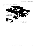
Loosen the captive fastener securing the latch mechanism to the front of the mini control unit. Pull the latch mechanism
away from the mini control unit (this will retract the latch mechanism located on the bottom of the mini control unit). This
unlocks the mini control unit from the shelf. Slide the mini control unit partially out from the shelf.
4.
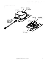
Carefully label the connectors plugged into the assembly. These connectors must be plugged into the same connectors on
the replacement assembly.
5.
Unplug all connectors plugged into the assembly.
6.
Replace the defective assembly with the new assembly.
7.
Plug all connectors removed from the old assembly into the same position on the replacement assembly.
8.
Slide the mini control unit completely into its mounting position. Push the latch mechanism into the front panel of the mini
control unit, and secure by tightening the captive fastener. This locks the mini control unit securely to the shelf.
9.
Remove the grounding wrist strap.
10.
To verify that the IB4 board is functioning, verify the mini control unit IP address is 192.168.100.100 as follows. From the Main
Screen on the mini control unit local display, press the ESC button, then the ENT key repeatedly until the IP address is
displayed. Verify the displayed IP address is 192.168.100.100.
11.
Enable the external alarms, or notify appropriate personnel that this procedure is finished.
12.
Ensure that there are no local or remote alarms active on the system.


