Vertiv
|
NetSure™ 2100 Series -48 VDC Power System Installation Manual (IM582138000)
|
Rev. C
64
Load Distribution Wiring, Input Battery Wiring, and CO Ground Wiring to List BA
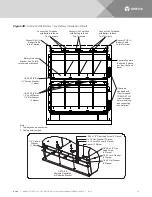
. Cut off perforated areas of shield as required for exiting leads from shelf.
Central Office (CO) Ground Wiring
Landing points are provided on the battery return bus for a central office ground lead. Refer to
stud size/spacing and recommended torque. For central office grounding requirements, refer to the current
edition of the American National Standards Institute (ANSI) approved National Fire Protection Association's
(NFPA) National Electrical Code (NEC), applicable local codes, and your specific site requirements.
Load Distribution Wiring to GMT Fuse Blocks
Load and load return leads are connected to screw-type terminal blocks located inside the distribution unit.
Refer to
for terminal block wire size capacity and recommended torque.
Feed wires from rear right side (as viewed from front) of shelf into distribution unit area. Secure distribution
wiring to rear of sheetmetal distribution unit slide. Leave slack in wires at rear to allow distribution unit to slide
in and out after wiring.
Load Distribution Wiring to Distribution Circuit Breakers
Load and load return leads are connected to screw-type terminal blocks located inside the distribution unit.
Refer to
for terminal block wire size capacity and recommended torque.
Feed wires from rear right side (as viewed from front) of shelf into distribution unit area. Secure distribution
wiring to rear of sheetmetal distribution unit slide. Leave slack in wires at rear to allow distribution unit to slide
in and out after wiring.
Input Battery Wiring
Input battery and battery return leads terminated in two-hole lugs are connected to threaded studs located on
the rear inside of the distribution unit. Refer to


