Vertiv
|
NetSure™ 2100 Series -48 VDC Power System Installation Manual (IM582138000)
|
Rev. C
72
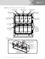
Figure 39:
List 93 and 94 Battery Tray Battery Installation Details
Note:
1. Two trays shown as example.
2. Cabling detail omitted.
Connect POS (+)
Battery Cable
to this Terminal
Spacers Separate
Batteries (3 places
per tray, front and
back)
Battery Retention
Bracket. See Detail A
for alternate orientation.
1/4-20 X 5/8” Bolt
1/4” Ground Washer
(1 place)
1/4-20 X 5/8” Bolt
1/4” Lock Washer
1/4” Flat Washer
(3 places)
Connect Link Furnished
with Battery to these
Two Terminals
If trays are
equipped with
circuit breakers,
TURN OFF ALL
circuit breakers
before installing
and connecting
any batteries!
Connect NEG (-)
Battery Cable
to this Terminal
Connect Link Furnished
with Battery to these
Two Terminals
Connect Link Furnished
with Battery to these
Two Terminals
DETAIL A
Alternate Orientation
of Retention Bracket
Spacer (3 Places)
No. 10 Lock Washer (3 Places)
10-32 x 1/2" Pan Head Screw (3 Places)
No. 10 Flat Washer (3 Places)
1/4" Ground
Washer
(1 Place)
1/4-20 x 5/8" Hex
Head Screw
(4 Places)
1/4-20 Lock Washer
(3 Places)
1/4-20 Flat Washer
(3 Places)


