Vertiv
|
NetSure -48V DC Bulk Output Power System Installation and User Instructions (UM582127100)
|
Rev. E
24
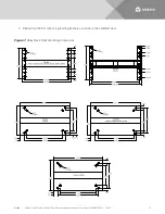
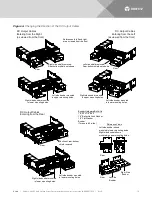
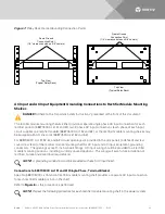
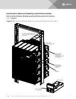
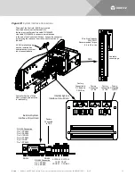
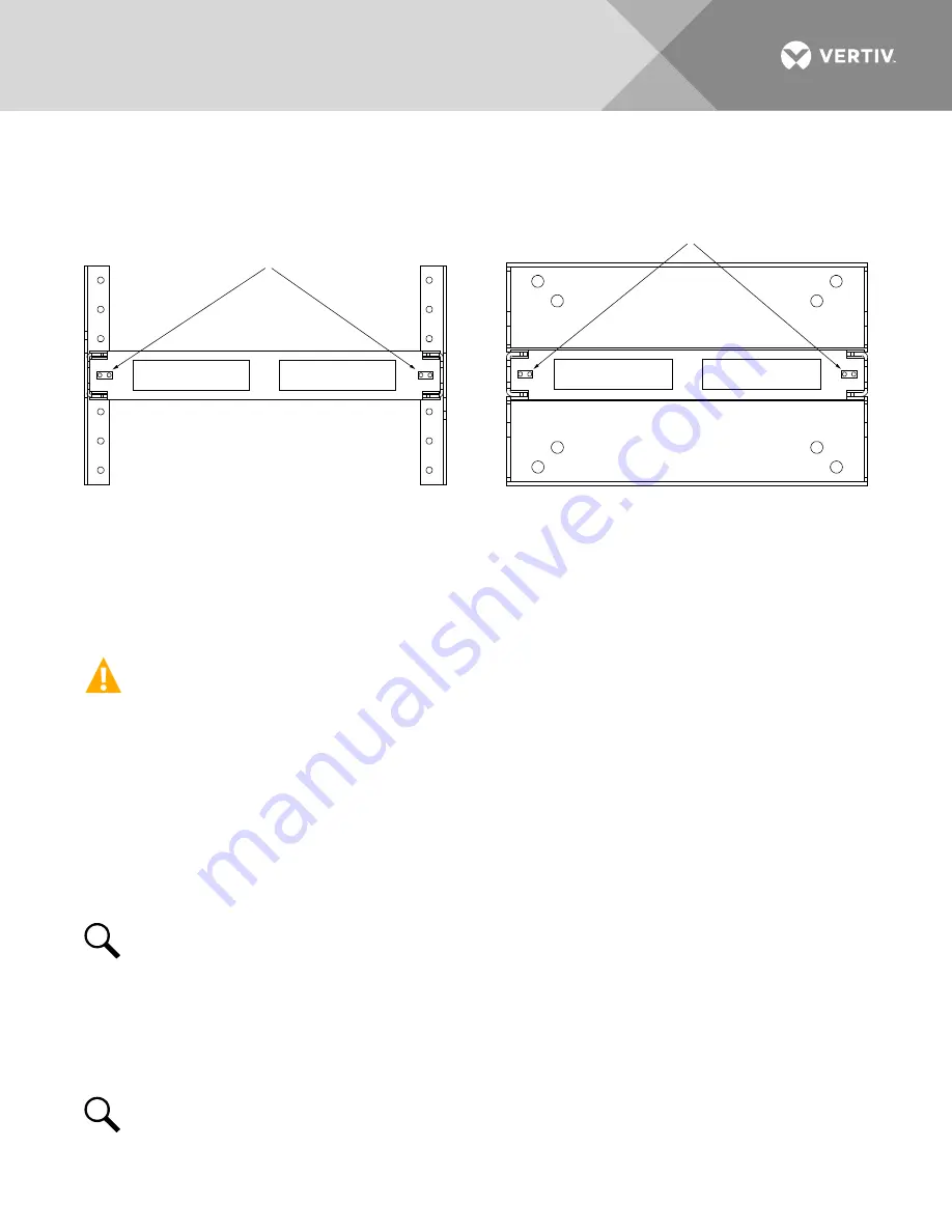
Figure 7:
Relay Rack Frame Grounding Connection Points
AC Input and AC Input Equipment Grounding Connections to Rectifier Module Mounting
Shelves
DANGER!
Adhere to the “Important Safety Instructions” presented at the front of this document.
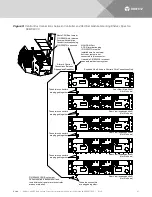
The rectifier module mounting shelves either provide a separate single phase AC input connection for each
rectifier position (588705000 List 51 and 61), two 3 phase AC input connections (each phase of each input
circuit supplies one rectifier module) (588705000 List 52 and 62), or the rectifier module mounting shelves may
be equipped with AC line cords (588705000 List 53 and 63).
For 588705000 List 51, 52, 61, and 62; circular openings are provided in the side panels (side feed) and rear
covers (rear feed) of the rectifier module mounting shelf for AC input and AC input equipment-grounding
conductors. The openings accept 1-inch conduit fittings. AC input wiring should be provided to all rectifier
module mounting positions, including currently unused positions. This wiring will ease future installation of
rectifiers to meet increased load requirements.
NOTE!
A grounding conductor must be provided with each AC input feed.
Connections to 588705000 List 51 and 61 (Single-Phase, Terminal Blocks)
Spec. No. 588705000 List 51 and 61 rectifier module mounting shelf provides a separate AC input connection
for each rectifier module position in the shelf.
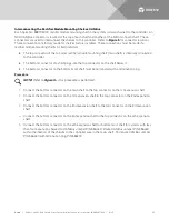
as this procedure is performed.
NOTE!
Repeat the following procedure for each rectifier module mounting shelf in the power system.
Frame Ground
Connection Point
(1/4” clearance holes on 5/8” centers)
Frame Ground
Connection Point
(1/4” clearance holes on 5/8” centers)
Top View
(Typical Relay Rack)
Top View
(Typical Relay Rack)


