Vertiv
|
NetSure -48V DC Bulk Output Power System Installation and User Instructions (UM582127100)
|
Rev. E
36
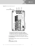
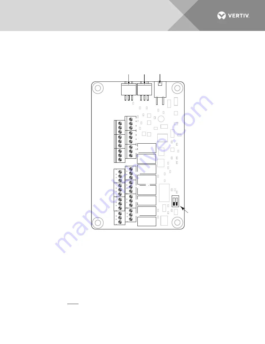
Figure 13:
IB2 (Interface Board) Connections
IB2
(Controller Interface Board)
Sw
itc
h s
et
tings
m
us
t be i
n t
hi
s po
si
tion
to i
nt
er
fac
e w
ith t
he C
ont
rol
ler
-
J1
2
*
R
EL
AY
SW1
7
J2
J1
1
5
3
1
R
el
ay
O
ut
put
T
er
m
inal
B
loc
ks
D
igi
tal
Input
T
er
m
inal
B
loc
ks
J9
J8
J7
J6
J5
J4
J3
8
6
4
2
8
7
6
5
4
3
2
1
+
IB
2 B
oar
d (
Top V
iew
)
NO
C
NC
NO
C
NC
NO
C
NC
NO
C
NC
NO
C
NC
NO
C
NC
NO
C
NC
NO
C
NC
5
3
1
4
6
2
5
3
1
4
6
2
5
3
1
4
6
2
5
3
1
4
6
2
5
3
1
4
6
2
5
3
1
4
6
2
5
3
1
4
6
2
C
onnec
tor
to c
ont
rol
ler
IB2
T
EM
P
PR
O
BR
E 1
IB2
T
EM
P
PR
O
BE 2
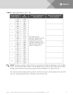
* The relay assigned to “Critical Summary” alarm (relay 1 by default)
will operate in the “Fail Safe Mode”. “Fail Safe Mode” means Relay 1 is
de-energized during an alarm condition, opening the contacts between the
C and NO terminals, and closing the contacts between the C and NC terminals.
The remaining seven (7) relays energize during an alarm condition, closing
the contacts between the C and NO terminals, and opening the contacts between
the C and NC terminals.
Not all I/O points are available for customer connection (some are used for factory
system connections).
J3-J9:
Wire Size Capacity: 16-26 AWG.
Recommended Torque: 2.2 in-lbs.

