Vertiv
|
NetSure -48V DC Bulk Output Power System Installation and User Instructions (UM582127100)
|
Rev. E
39
Controller CAN Bus
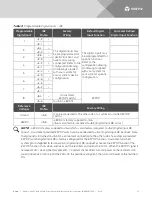
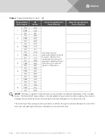
The end of the Controller CAN Bus is routed into the controller section of the main rectifier module mounting
shelf via cable P/N 556430. Use cable P/N 556238 to connect external devices to the end of the Controller
CAN bus. Access the Controller CAN Bus connector by removing the top cover from the controller section of
the main rectifier module mounting shelf. A CAN termination plug must be installed if an external device or
system is not connected here. Refer to
, and
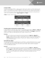
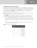
Table 5:
Controller CAN Bus Cables
P/N 556430 (Int. CAN) Cable
Signal
Wire Color
Pinouts
CAN-H
Black
CANx-1
CAN-L
Red
CANx-2
P/N 556238 (Ext. CAN) Cable
Signal
Wire Color
Pinouts
CAN-H
Black
CANx-1
CAN-L
Red
CANx-2
Connecting a Device or System to the Controller CAN Bus
A supporting device or system may be connected to the Controller CAN Port. Refer to
for location. A 10’ long Controller CAN Bus Cable is available (P/N 556238) to extend the end of the Controller
CAN Bus outside the main rectifier module mounting shelf to other equipment. See
and wire colors. Refer also to the external device’s or system’s instruction manual.
Procedure
1.
Remove the CAN termination plug from the Controller CAN Port (see
for
location). Connect the device or system to the Controller CAN Port using cable P/N 556238. Refer to
for cable pinouts and wire colors. Note that you may have to cut the end off of the cable if it is
not compatible with the device’s CAN Bus connection points. Refer also to the external device’s or
system’s instruction manual.
Optional SM-Temp Module
The analog output of the SM-Temp Module may be connected to a controller temperature port input. In lieu of
connecting the analog output of the SM-TEMP module to a controller temperature port input, the SM-TEMP
module can simply be connected at the end of the Controller CAN Bus. Refer to the SM-Temp Module
Instructions (UM547490) for details.
Procedure
1.
Remove the CAN termination plug from the Controller CAN Port (see
for
location). Connect the SM-Temp Module CAN Bus to the Controller CAN Port using cable P/N 556238.
Refer to
for cable pinouts and wire colors. Note that you will have to cut the end off of the cable
to connect it to the SM-Temp Module’s CAN Bus connection points. Ensure the last SM-Temp Module
(or if only one) has a CAN termination strap as shown in the SM-Temp Module Instructions
(UM547490).

