Vertiv
|
200 A Distribution Fuse Panel Assembly Installation & User Manual (UM563317)
|
Rev. B
20
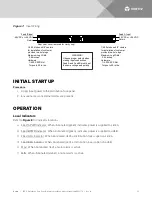
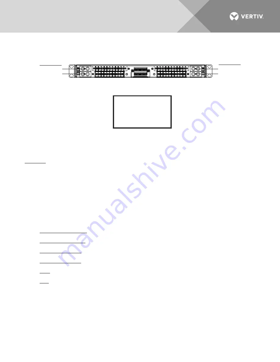
Figure 7:
Input Wiring
INITIAL STARTUP
Procedure
1.
Apply input power to the distribution fuse panel.
2.
Ensure no local or external alarms are present.
OPERATION
Local Indicators
a)
Feed A PWR Indicator: When illuminated (green), indicates power is supplied to side A.
b)
Feed B PWR Indicator: When illuminated (green), indicates power is supplied to side B.
c)
Feed A FA Indicator: When illuminated (red), a distribution fuse is open on side A.
d)
Feed B FA Indicator: When illuminated (red), a distribution fuse is open on side B.
e)
MAJ: When illuminated (red), a major alarm is active.
f)
MIN: When illuminated (amber), a minor alarm is active.
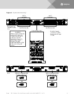
1/4-20 studs on 5/8” centers
for installation of customer
provided two-hole lugs.
Maximum Lug Width:
0.64 inches.
Hardware:
1/4-20 KEPS Nut
Torque to 50 in-lbs.
1/4-20 studs on 5/8” centers
for installation of customer
provided two-hole lugs.
Maximum Lug Width:
0.64 inches.
Hardware:
1/4-20 KEPS Nut
Torque to 50 in-lbs.
Rear (rear cover removed for clarity only)
Feed B Input
-48 VDC or +24 VDC
Return
Feed A Input
-48 VDC or +24 VDC
Return
WARNING!
Observe proper polarity when
making input connections.
Feed A and Feed B must be of
the same voltage and polarity.
Summary of Contents for NetSure NSFP200
Page 24: ...UM563317 RB 05 17...


