background image


Vertiv


|


Aerial Ultracab Cross-Connect Enclosures (631-201-009)


|


Rev. F 

16 

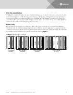
Wire Pair Identification 

The feeder (in) and distribution (out) pairs are identified separately on the face of the enclosure blocks by color 
code. The binding posts or IDC clips are given terminal pair identification, starting with one and proceeding to 
the last pair number for that particular type of pair. Therefore, each has a feeder (in-green) pair number one 
and a distribution (out-blue) pair number one, etc. Terminal blocks are numbered horizontally (EXAMPLE: Row 
1, pairs 1-5; row 2, pairs 6-10; on RLS: Row 1, pairs 1-10; etc.). 
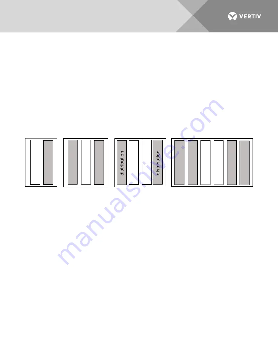
Feeder Pairs 

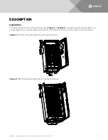
All standard pole-mounted cross-connect enclosures of 600 pairs and larger are configured for a feeder to 
distribution ratio of 1 to 2. Engineering design may dictate different counts. Feeder pairs are located in the left 
column for 100-pair to 400-pair enclosures; in the center column for 600-pair to 900-pair enclosures and in the 
two center columns for 1200-pair to 2700-pair enclosures. Refer t

Figure 4

Figure 4:  

Layout of Terminal Blocks 


fe

ed

er

di

st

rib

ut

io

n

100 - 400 pair

enclosure

fe

ed

er

di

st

rib

ut

io

n

di

st

rib

ut

io

n

600 - 900 pair

enclosure

fe

ed

er

fe

ed

er

di

st

rib

ut

io

n

di

st

rib

ut

io

n

di

st

rib

ut

io

n

di

st

rib

ut

io

n

1900 - 2700 pair

enclosure

fe

ed

er

fe

ed

er

1200 - 1800 pair

enclosure

Summary of Contents for Ultracab Cross-Connect

Page 1: ...Aerial Distribution Products Aerial Ultracab Cross Connect Enclosures Description and Installation Manual 631 201 009 Revision F Part Number P71350...

Page 2: ...materials to be used in performing procedures not specifically described in this document This document may contain confidential and or proprietary information of Vertiv Group Corporation and its rece...

Page 3: ...d Replacement Procedures 10 Static Warning 11 About this Document 13 Purpose 13 Reason for Reissue 13 Information Not Provided in This Practice 13 Description 14 Application 14 Construction 15 Termina...

Page 4: ...ided ANSI OSHA This admonition is not used for situations that pose a risk only to equipment data or service even if such use appears to be permitted in some of the applicable standards OSHA ALERT Ale...

Page 5: ...ID A to all ground connections Insulation of field wire conductors should be rated no less than 105 C and gauge in a manner that is consistent with the NEC and local codes Always use a non contact vol...

Page 6: ...able of producing fatal electrical shock AC input power must be completely disconnected from the branch circuits wiring used to provide power to the system before any AC electrical connections are mad...

Page 7: ...ISK OF ELECTRIC SHOCK The DC bus is powered by DUAL power sources Rectifiers and DC Batteries To properly work on the system de energize by disconnecting BOTH power sources Even with the batteries tur...

Page 8: ...se slings clevises or shackles of insufficient capacity Crane Operation Only properly trained operators shall operate the crane Do not operate the crane until all stabilizers are extended The stabiliz...

Page 9: ...INJURY TO EYES AND SKIN FROM OPTIC DEVICES Do not look into a fiber cable or device nor hold such cable or device against body fabric or other material WARNING RISK OF HAZARDOUS SUBSTANCES After hand...

Page 10: ...oper PPE Only authorized and properly trained personnel should be allowed to install inspect operate or maintain the equipment Do not work on LIVE parts If required to work or operate live parts obtai...

Page 11: ...Read and follow wrist strap manufacturer s instructions outlining use of a specific wrist strap 3 Do not touch traces or components on equipment containing static sensitive components Handle equipmen...

Page 12: ...Vertiv Aerial Ultracab Cross Connect Enclosures 631 201 009 Rev F 12 This page is intentionally blank...

Page 13: ...al practices or building codes as applicable for the correct methods tools and materials to be used in performing procedures not specifically described in this document If your enclosure is equipped w...

Page 14: ...acab Cross Connect Enclosures Figure 1 and Figure 2 are pole mounted center feed cross connect interface system equipped with quiet front CFQ terminal blocks or RLS self strip terminal blocks Figure 1...

Page 15: ...000 1200 45 32 14 1300 1800 62 33 14 1900 2700 62 46 14 Terminal Blocks The terminal block field is drop down style and secured with hex head bolts All blocks are hard wired to a cable stub or harness...

Page 16: ...1 5 row 2 pairs 6 10 on RLS Row 1 pairs 1 10 etc Feeder Pairs All standard pole mounted cross connect enclosures of 600 pairs and larger are configured for a feeder to distribution ratio of 1 to 2 En...

Page 17: ...below aerial cables with adequate clearance for bending the stub at a 90o angle to prepare the splice A balcony may be installed for ease of access and to provide a safe working position for field te...

Page 18: ...that both brackets on the enclosure are properly engaged and sitting levelled on the pole bracket see Figure 6 5 Secure the bottom pole mounting by drilling a 11 16 inch hole through the pole and usi...

Page 19: ...Vertiv Aerial Ultracab Cross Connect Enclosures 631 201 009 Rev F 19 Figure 7 Bottom Pole Mounting Bracket...

Page 20: ...Blocks or Terminating Jumper Wires on RLS Blocks Terminating Jumper Wires on CQF Blocks Perform the following steps to terminate a jumper wire pair on a CQF terminal block in the feeder field 1 Pull...

Page 21: ...g Jumper Wires on RLS Blocks For specific information on terminating wire pairs on RLS blocks see document 641 202 002 RLS50 Self Strip Block Description and Installation For information on dual wire...

Page 22: ...Figure 11 Figure 11 Routing Wire 2 Place the wire behind the wire retainers at the sides or bottom of the terminal field and make a finger loop in the wire to provide enough slack to trace the wires...

Page 23: ...er CQF block numbers 1500 2700 P49941 blue distribution CQF block numbers 2701 3600 P44196 blue distribution CQF block numbers 1 2700 P64541 green feeder RLS block numbers 1 2100 P53350 blue distribut...

Page 24: ...s that fit over the silos surrounding the binding posts or activators see Figure 14 A package with eighty pairs of caps is furnished with each terminal Label Kits for the Terminal Blocks These are ava...

Page 25: ...Vertiv Aerial Ultracab Cross Connect Enclosures 631 201 009 Rev F 25 This page is intentionally blank...

Page 26: ...VertivCo com Vertiv Headquarters 1050 Dearborn Drive Columbus OH 43085 USA 631 201 009 RF 10 17...

Reviews: