10
•
When carrying the tile saw, hold only by transport handles, do not
hold by saw shields.
CAUTION! This device is designed to operate indoors.
The design is assumed to be safe, protection measures and
additional safety systems are used, nevertheless there is always
a small risk of operational injuries.
CONSTRUCTION AND USE
Ceramic tile saw is designed for dry and wet cutting of small and
medium ceramic tiles, appropriate for size of the tile saw. The tile saw
must not be used for cutting wood or metal. Use only cutting blades
designed for ceramic tile saw. Do not use segmented cutting discs.
Ceramic tile saw is designed for all works from the range of individual,
amateur activities (tinkering). It is not intended for professional use.
Use the tool according to its purpose only.
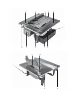
DESCRIPTION OF DRAWING PAGES
Below enumeration refers to the device elements depicted on the
drawing pages of this manual.
1.
Fence
2.
Angle bar
3.
Cutting blade shield
4.
Fixing knob for cutting blade shield
5.
Work table
6.
Cutting blade bottom shield
7.
Water container
8.
Work table locking knob
9.
Switch
10.
Fence fixing knob
11.
Cutting blade
12.
Support for cutting blade shield
13.
Power indicator
14.
RESET button
15.
TEST button
* Differences may appear between the product and drawing.
MEANING OF SYMBOLS
CAUTION
WARNING
ASSEMBLY/SETTINGS
INFORMATION
EQUIPMENT AND ACCESSORIES
1. Rip fence
- 1 pce
2
. Screw + washer
-
2
sets
3
. Angle bar
- 1 pce
4
. Water container
- 1 pce
5
. Ring spanner
-
2
pcs
PREPARATION FOR OPERATION
SAW INSTALLATION ON A WORKSHOP BENCH
It is recommended to firmly fix the tile saw to a workbench with the
use of mount holes designed for such purpose. They are located on
the tile saw base and guarantee safe operation and eliminate risk of
unwanted machine shifts during operation.
INSTALLATION OF CUTTING BLADE SHIELD
Disconnect the tool from power supply.
•
Put cutting blade shield (
3
) on the support for cutting blade shield
(
12
).
•
Put the fixing knob for cutting blade shield (
4
) into hole in the
cutting blade shield (
3
) and hole in the support for cutting blade
shield (
12
), then tighten.
•
You can remove the cutting blade shield (
3
) by following above
procedure in reverse sequence.
FENCE INSTALLATION
Disconnect the tool from power supply.
•
Install fence fixing knobs (
10
) and washers to the fence (
1
).
•
Slide the fence (
1
) into slots in the work table (
5
).
•
Set required cutting width using scales located on the work table
top (
5
).
•
Tighten fence fixing knobs (
10
).
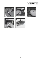
SETTING SUPPORT FOR CUTTING BLADE SHIELD
Disconnect the tool from power supply.
•
Loosen fixing screws (
a
) of the support for cutting blade shield (
12
)
(
fig. A
).
•
Set the support for cutting blade shield (
12
) so the distance
between cutting blade (
11
) and support for cutting blade shield
(
12
) is
3
–
5
mm (
fig. A
).
•
Support for cutting blade shield (
12
) should be located precisely on
longitudinal axis of the cutting blade (
11
) plane.
•
Tighten fixing screws (
a
) of the support for cutting blade shield (
12
).
•
Install the cutting blade shield (
3
).
Check position of the support for cutting blade shield after each
replacement of the cutting blade.
OPERATION / SETTINGS
Ensure the tile saw is disconnected from power supply network
before starting any adjustments. To ensure safe, precise and
efficient tile saw operation, proceed with all adjustment
procedures as a whole.
After finishing all the setting and adjustment procedures
ensure that all adjustment keys are collected. Check that all
threaded joining elements are properly tightened. When making
adjustments ensure that all external parts work properly and
are in good condition. Any worn out or damaged part must be
replaced by qualified personnel before starting to use the tile
saw.
Plug of the power supply cord of the tile saw is equipped with
residual current protection device. Check operation of the
residual current device before starting to use the tool.
•
Put the plug into power supply socket, the power indicator (
13
) will
switch on (
fig. E
).
•
Press
TEST
button (
15
) – the power indicator (
13
) will switch off.
•
Press
RESET
button (
14
) – the power indicator (
13
) will switch on
again.
If the residual current device is faulty (it does not operate as
described above) you must remove power cord plug from the
Summary of Contents for 52G281
Page 2: ...1 12 11 3 2 4 6 7 8 9 10 10 8 5...
Page 3: ...3 A a 3 5mm 12 11 B b 9 8 C c 6 D 11 e d E 14 15 13...
Page 16: ...16 1 2 3 4 5 6 7 8 9 10 11 12 13 14 RESET 15 TEST 1 1 2 2 3 1 4 1 5 2 3 12 4 3 12...
Page 19: ...19 52G281 30 30 UA 1 2 3 4 5 6 7 8 9 10 11 12 13 14 RESET 15 TEST...
Page 48: ...48 1 2 3 4 5 6 7 8 9 10 11 12 13 14 RESET 15 TEST 1 1 2 2 3 1 4 1 5 2 3 12 4 3 12 3...
Page 58: ...58 1 2 3 4 5 6 7 8 9 10 11 12 13 14 RESET 15 TEST...
Page 60: ...60 8 5 b B 8 1 1 11 450 450 1 2 2 1 1 10 2 1 11 7 6 7 6 c C 6 d D e 11 6 6 c...
Page 68: ......


