2019/05/01 00:16
3/17
OEM Integration Guide
Product Manuals - http://www.vescent.com/manuals/
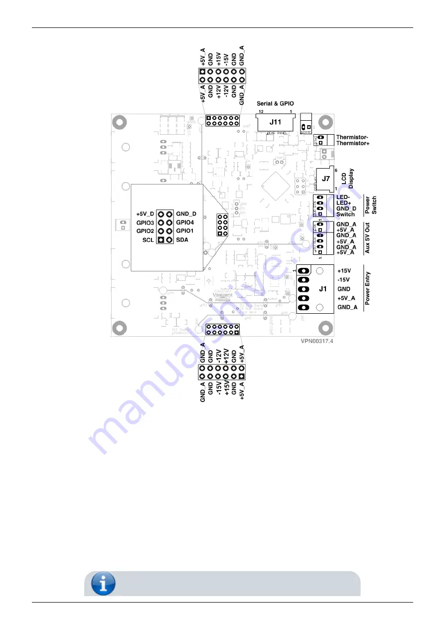
Fig. 3: ICE-MC1 Master and Control Board connector schematic (as viewed from component side).
Power Entry Through ICE Master Controller
Power is provided at J1 (
path for +5V_A is GND_A. This wiring connected to this return path should be capable of carrying the
maximum current of the +5V_A line. Since the master controller handles all
, the power connections for 5V_A, +15V, and -15V can be applied in any order so long as
both ground connections have been established. The master controller will not turn on if any of the
required voltages are not present or are out of range. These power entry inputs are also reverse-
polarity protected. When the master controller enables power to the daughter boards via the power
bus, power is in-rush current limited to less than 10A on the 5V_A line and 3A on the 15V lines.


