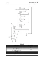
Specification
Desc./Quantity
11
Electric fan starter
The Lambda sensor or oxygen sensor is a sensor which provides indications concerning the oxygen
content in the exhaust gas. The signal generated is not of the proportional type but of the ON/OFF type,
i.e. there is oxygen or there is not. The sensor is positioned on the exhaust manifold before the catalytic
converter in an area where the gas temperature is always high. The temperature at which the sensor
works is at least 350°C at 600°C and it has a reaction time of just 50 milliseconds. The signal generated
passes from a high value to a low value with a mixture with lambda =1. Since the sensor only works at
high temperatures, it has an electric preheating element inside it, controlled by the control unit, to take
it quickly to the functioning state.
Specific tooling
020481Y
Control unit interface wiring
020331Y
Digital multimeter
Check that the injection load 10A fuse No. 3 is in
good conditions.
Check that the 7.5A fuse No. 2 for the live control
unit is in good conditions.
Check the presence of voltage between pins 21
and 26 of the interface wiring for around two sec-
onds, switching to "ON"
With the engine cold, check the resistance of the
Lambda sensor heater between pin 21 of the in-
terface wiring and the green black cable of the
injection load remote control base with the control
unit disconnected and the remote control discon-
nected.
Resistance of the heater at approximately 20° = 9
Ohm ± 20%
Injection
Vespa GTS 250 I.E.
INJEC - 48
Summary of Contents for GTS 250 I.E.
Page 1: ...WORKSHOP MANUAL 633577 Vespa GTS 250 I E ...
Page 4: ......
Page 6: ......
Page 7: ...INDEX OF TOPICS CHARACTERISTICS CHAR ...
Page 19: ...INDEX OF TOPICS TOOLING TOOL ...
Page 32: ...Tooling Vespa GTS 250 I E TOOL 14 ...
Page 33: ...INDEX OF TOPICS MAINTENANCE MAIN ...
Page 47: ...INDEX OF TOPICS TROUBLESHOOTING TROUBL ...
Page 51: ...INDEX OF TOPICS ELECTRICAL SYSTEM ELE SYS ...
Page 56: ...Front side 1 Saddle opening switch 2 Wirings Electrical system Vespa GTS 250 I E ELE SYS 6 ...
Page 90: ... Refit the battery cover Connectors Electrical system Vespa GTS 250 I E ELE SYS 40 ...
Page 91: ...INDEX OF TOPICS ENGINE FROM VEHICLE ENG VE ...
Page 98: ...Engine from vehicle Vespa GTS 250 I E ENG VE 8 ...
Page 99: ...INDEX OF TOPICS ENGINE ENG ...
Page 156: ...Engine Vespa GTS 250 I E ENG 58 ...
Page 164: ...Engine Vespa GTS 250 I E ENG 66 ...
Page 165: ...INDEX OF TOPICS INJECTION INJEC ...
Page 168: ...Injection Vespa GTS 250 I E INJEC 4 ...
Page 184: ... REMOTE CONTROLS CONTROL UNIT FUSES ETC Injection Vespa GTS 250 I E INJEC 20 ...
Page 198: ...Components location Injection Vespa GTS 250 I E INJEC 34 ...
Page 204: ...Injection Vespa GTS 250 I E INJEC 40 ...
Page 218: ...Injection Vespa GTS 250 I E INJEC 54 ...
Page 219: ...INDEX OF TOPICS SUSPENSIONS SUSP ...
Page 240: ...Suspensions Vespa GTS 250 I E SUSP 22 ...
Page 241: ...INDEX OF TOPICS BRAKING SYSTEM BRAK SYS ...
Page 257: ...INDEX OF TOPICS COOLING SYSTEM COOL SYS ...
Page 260: ...Cooling system Vespa GTS 250 I E COOL SYS 4 ...
Page 261: ...INDEX OF TOPICS CHASSIS CHAS ...
Page 273: ...INDEX OF TOPICS PRE DELIVERY PRE DE ...
Page 277: ...INDEX OF TOPICS TIME TIME ...


