background image

EN

Contents

2

Contents

Introduction  .......................................................................... 3
Questions and FAQs ............................................................. 3
Register Your Cortex ............................................................ 3
Required components ......................................................... 4
Optional accessories ........................................................... 4
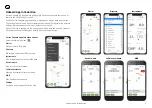
Onboard App Introduction .................................................. 5
The Cortex network .............................................................. 6
LED indicator panel .............................................................. 7
Cortex Hub port locations................................................... 7
Cortex Hub positioning ........................................................ 8
Cortex Hub mounting .......................................................... 8
To connect power ................................................................. 9
Wiring color codes ............................................................ 9
AIS / VHF Antenna .............................................................. 10
What does VSWR mean? ................................................... 10
Internal AIS / VHF splitter .................................................. 11
AIS / VHF Antenna connection ......................................... 11
External GPS Antenna......................................................... 11
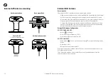
External GPS Antenna mounting ...................................... 12
External WiFi Antenna ........................................................ 12
External WiFi Antenna installation ................................... 13
NMEA 2000 Gateway .......................................................... 13
To connect to NMEA 2000................................................. 14
To connect to NMEA 0183................................................. 15
External Cellular Antenna ................................................... 16
External Speaker .................................................................. 17

Vesper Marine External Speaker ...................................... 17
External Loudspeaker ......................................................... 18
Connecting devices to an Cortex Hub ............................. 19
To connect a mobile device ............................................... 19
To connect a handset ......................................................... 20
Device connection FAQs .................................................... 20
MMSI programming Introduction ..................................... 21
MMSI Programming Warning ........................................... 21
To program an MMSI with the Onboard App ................. 21
To program an MMSI with a handset .............................. 22

To confirm AIS operation

 ................................................... 22

Monitoring and control ....................................................... 23
Cortex Monitor App Introduction ...................................... 23
To program GPIO sensors with the Cortex Onboard App 

24
To program GPIO sensors with a Cortex Handset ........ 24
Heading Sensor ................................................................... 25

To update Cortex Hub firmware

 ....................................... 25

Cortex Hub Wiring color codes ......................................... 26
GPIO sensor wiring - Alarm silence switch ..................... 27
GPIO sensor wiring - Lighting remote control ................ 28
GPIO sensor wiring - Motion sensor ................................ 29
GPIO sensor wiring - High water sensor ......................... 30
GPIO sensor wiring - Bilge pump activation sensor ..... 31
GPIO sensor wiring - Hatch / door open sensor ............ 32
GPIO sensor wiring - Smoke / Heat sensor .................... 33
Dimensions ........................................................................... 34

Specifications

 ....................................................................... 35

Dimensions LED icon troubleshooting .......................... 37
Warnings ............................................................................... 39
Warranty ................................................................................ 41

Summary of Contents for Cortex HV1

Page 1: ...HUB INSTALLATION GUIDE Cortex Hub USA USA CANADA Cortex Hub ROW REST OF WORLD ...

Page 2: ...18 Connecting devices to an Cortex Hub 19 To connect a mobile device 19 To connect a handset 20 Device connection FAQs 20 MMSI programming Introduction 21 MMSI Programming Warning 21 To program an MMSI with the Onboard App 21 To program an MMSI with a handset 22 To confirm AIS operation 22 Monitoring and control 23 Cortex Monitor App Introduction 23 To program GPIO sensors with the Cortex Onboard ...

Page 3: ...uded with the option to attach external antennas as required Off boat vessel monitoring and control is supported via a built in cellular modem and the Cortex Monitor App on your phone Integrated sensors provide vessel position battery voltage heading and barometric pressure while NMEA 2000 or NMEA 0183 provides information from sensors connected to the NMEA network Optional external sensors can be...

Page 4: ... components Not included AIS VHF antenna Fuse or circuit breaker Fastenings of your choice Mobile device running the Cortex Onboard App or a Cortex Handset for configuring Optional accessories Cortex H1 or H1P handset s External audio and loudspeaker External cellular antenna NMEA 2000 cable NMEA 2000 Tee connector NMEA 2000 network extension cable External sensors for Monitoring and Control ...

Page 5: ...up Once the Cortex is configured the Cortex Onboard App acts like a Cortex Handset offering access to most functions directly from your smart device Cortex Onboard App Main Menu options Select the Main Menu icon Plotter Plotter view of AIS targets Directory AIS targets and manual DSC contacts Instruments GPS integrated sensors and NMEA data Anchor watch Monitor the vessel at anchor Collision avoid...

Page 6: ...FI WIFI CELL Secondary VHF GPS 10 Hz Antenna included WiFi data AIS VHF Antenna WiFi Antenna included WiFi Antenna included Cellular Antenna Cortex Monitor App Cortex Handsets Cortex Onboard App External Speaker NMEA 0183 Devices NMEA 2000 Devices ...

Page 7: ... a functioning subsystem with Orange and Red indicating a connection configuration or other issue that may need to be resolved Power ON is indicated with white light See LED indicator panel on page 22 for a full troubleshooting list Power Cloud NMEA 2000 WiFi VHF GPS Cortex Hub port locations 1 WiFi Antenna port 2 GPS Antenna port 3 Cellularv Antenna port 4 DC Power Supply 12V or 24V DC 5 Auxiliar...

Page 8: ... the minimum safe compass distance is maintained Standard 0 8 m Steering 0 4 m Cables Allow 2 50mm Cables Allow 2 50mm WiFi Antenna Allow 8 200mm Cortex Hub mounting 1 Use the Cortex Hub as a template for mounting holes 2 Mark the holes on the mounting surface and drill them 3 Align the Cortex Hub to the mounting holes and secure with fastenings of your choice not included Recommended screws 316 S...

Page 9: ... cable to the Cortex Hub Tighten the power cable lock ring clockwise to ensure a secure connection and watertight seal 5 Turn the vessel s batteries and or switch or circuit breaker on to apply power to the Cortex Hub 6 Confirm the Cortex Hub is powered on with a visual check on the Cortex Hub indicator lights 24 Hour Circuit Leaving Cortex powered on a 24 hour circuit will ensure Cortex can conti...

Page 10: ...quate separation may damage the Cortex transponder and void your warranty Never operate the Cortex Hub unless it is connected directly to a suitable VHF antenna The VHF indicator light will display red when a problem is detected with the antenna system ie the VSWR is above the acceptable level What does VSWR mean VSWR stands for Voltage Standing Wave Ratio and is a measure of the how well matched ...

Page 11: ...ths and determine the best location for mounting the external GPS antenna The Vesper Marine GPS antenna is specifically designed for use with Vesper Marine devices Use of a different GPS antenna may damage the Cortex Hub and void the warranty After installing the GPS Antenna connect the SMA connector of the GPS Antenna cable to the Cortex Hub port labeled GPS Hand tighten clockwise Do not over tor...

Page 12: ...nboard Some objects and materials such as steel aluminum and carbon composites may provide interference to degrade the WiFi signal strength External Wifi Antenna Configuration CORTEX ONBOARD APP Menu Settings Device Settings Networks WiFi Use external antenna select on off CORTEX HANDSET Main Menu Touch on the wrench icon to open the Configuration Menu Networks WiFi External Antenna select on off ...

Page 13: ...translates selected NMEA 2000 sensor data for compatibility with mobile apps Monitor navigation data on your Cortex Onboard App on your phone or tablet or use it with third party apps of your choice Data is made available to NMEA 0183 and 2000 plotters The Gateway supports a range of wind depth speed heading temperature barometric pressure and autopilot PGNs See PGNs sent and received by the gatew...

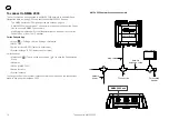
Page 14: ...Modifying the Instance or System Identification can be done via the Cortex Onboard App or from the H1 handset Cortex Onboard App Menu Settings Device Settings Networks NMEA 2000 Device Instance 0 255 select to enter value System Instance 0 255 select to enter value Cortex handset Main Menu Touch on the wrench icon to open the Configuration Menu Networks N2000 NMEA 2000 Device Instance System Insta...

Page 15: ...e select Cortex handset Main Menu Touch on the wrench icon to open the Configuration Menu Networks 0183 NMEA 0183 Baud In Baud out AIS output requires a minimum of 38400 Baud rate When connecting the Cortex Hub to NMEA 0183 devices connect 0183 Common Black to the vessel s negative bus This is to ensure a satisfactory grounding as the NMEA 0183 network of the Cortex Hub is isolated POWER VE POWER ...

Page 16: ...ing through holes and openings Do not cut the cable without the correct tools to crimp on a new connector Do not extend the antenna cable beyond the supplied length of 5M 16 A solid orange light on the LED indicator panel indicates an attempt to connect to a cell tower green indicates connection See LED indicator panel on page 22 External Antenna Configuration Cortex Onboard App Menu Settings Devi...

Page 17: ...ve Red Loudspeaker Positive Brown Loudspeaker Negative External Speaker Wiring Diagram BROWN RED LOUDSPEAKER LOUDSPEAKER BLACK AUDIO SPEAKER ORANGE AUDIO SPEAKER O SPEAKER O SPEAKER Vesper Marine External Speaker The Vesper Marine External Speaker Part Number 111210 is purpose designed for the marine environment Featuring IP66 ingress protection this speaker is suitable for installing almost anywh...

Page 18: ...tting Loudspeaker Volume Loudspeaker volume will default to Mute To set the desired volume use a Cortex Handset of the Cortex Onboard App Setting Loudspeaker Tone You can also set the pitch the horn will use between 200 500Hz from the Horn and Hailer settings Audio Cable Wiring Code Orange Audio Speaker Positive Black Audio Speaker Negative Red Loudspeaker Positive Brown Loudspeaker Negative Exter...

Page 19: ...ting devices to use the NMEA 2000 data from an Cortex Hub over WiFi Connection information Connection Type TCP IP Address 10 1 1 1 Port 39150 To connect a mobile device 1 Turn Cortex Cortex Hub and device ON Switch the vessel s batteries ON to power the Cortex Hub 2 Select WiFi in the settings of the device From the list of available WiFi identify and select the Cortex Hub WiFi SSID Note The WiFi ...

Page 20: ...dset or mobile device displays Trying to connect for a long period it has not made a WiFi connection to the Cortex Hub Confirm the Cortex Hub is ON Check the WiFi signal strength on the mobile device or in the Status Bar of the handset Check the Cortex Hub WiFi External Antenna is attached Consider the distance between the device and Cortex Hub on board Some objects and materials may provide inter...

Page 21: ...ation of the rules of the Federal Communications Commission to input an MMSI that has not been properly assigned to the end user or to otherwise input any inaccurate data in this device To program an MMSI with the Onboard App 1 Download the Cortex Onboard App Free download from the Apple or Google Play stores 2 Turn Cortex Cortex Hub and device ON Switch the vessel s batteries ON to power the Cort...

Page 22: ... Cortex Cortex Hub and handset ON Switch the vessel s batteries ON to power the Cortex Hub 2 Connect the handset to the Cortex Hub via WiFi See Connecting to an Cortex Hub section 3 Select the handset Main Menu and program as follows Main Menu Select the wrench icon to open the Configuration Menu Vessel Vessel Identification MMSI Enter MMSI number Name Enter the vessel s name Callsign Enter the ve...

Page 23: ... Cortex Hub is connected to an NMEA 2000 bus data from applicable NMEA 2000 and 0183 devices will display on the handset and Onboard App Instruments screen and on the Cortex Monitor App See NMEA PGNs and Monitoring Instruments on page 26 for PGN sentences sent and received Cortex Monitor App Introduction Cortex Monitor is a free Apple iOS and Android app that allows your phone to monitor and contr...

Page 24: ...onnecting GPIO sensors to the Cortex Hub When a sensor does not provide more than 2V the Pullup provides an appropriate high level reference for the Cortex Hub s input To program GPIO sensors with a Cortex Handset Name and configure up to 5 general purpose sensors 3 x input 2 x input output 1 Turn Cortex Cortex Hub and handset ON Switch the vessels batteries ON to power the Cortex Hub 2 Connect th...

Page 25: ...evice Settings Sensors Heading With a handset 1 Turn Cortex Cortex Hub and handset ON Switch the vessel s batteries ON to power the Cortex Hub 2 Connect the handset to the Cortex Hub via WiFi See Connecting to an Cortex Hub section 3 Select the handset Main Menu and program as follows Main Menu Select the wrench icon to open the Configuration Menu Sensors Heading To update Cortex Hub firmware Firm...

Page 26: ...Class B CS Static Part A 129810 AIS Class B CS Static Part B 130306 Wind data MWD MWV NMEA PGNs and Monitoring Instruments Received PGNs are translated and outputted over NMEA 0183 and WiFi See support vespermarine com for an up to date list Received PGNs PGN DESCRIPTION TRANSLATED TO 0183 INSTRUMENTS DATA SOURCE 127250 Vessel Heading HDG Yes 128259 Speed water referenced VHW Yes 128267 Water dept...

Page 27: ...RANGE BLACK RED BROWN LIGHT GREEN INPUT OUTPUT 5 BROWN INPUT OUTPUT 4 GRAY INPUT 3 VIOLET INPUT 2 BLUE INPUT 1 RED PULLUP VOLTAGE NMEA TX B NMEA TX A NMEA RX B NMEA RX A AUDIO VE AUDIO VE LOUDSPEAKER VE LOUDSPEAKER VE BLACK RED POWER VE POWER VE BLACK NMEA 0183 COMMON and GPIO GROUND ...

Page 28: ... level reference for the Cortex Hub s input ve 12 24V ve LIGHT GREEN BROWN GRAY VIOLET BLUE BLACK INPUT 3 INPUT 2 BLACK BROWN RED INPUT 1 GPIO GND RED PULLUP VOLTAGE INPUT OUTPUT 2 INPUT OUTPUT 1 Vesper Marine Momentary External Mute Switch Part Number 141025 Switch Illumination Red ve Optional P N 141025 GPIO sensor configuration example Sensor control name Silence Sensor control type Alarm silen...

Page 29: ...ended when connecting GPIO sensors to the Cortex Hub When a sensor does not provide more than 2V the Pullup provides an appropriate high level reference for the Cortex Hub s input LIGHT GREEN BROWN GRAY VIOLET BLUE BLACK INPUT 3 INPUT 2 INPUT 1 GPIO GND RED PULLUP VOLTAGE INPUT 5 INPUT 4 Output relay Light ve 12 24V NO C C ve ve ve GPIO sensor configuration example Sensor control name Anchor light...

Page 30: ...an 2V the Pullup provides an appropriate high level reference for the Cortex Hub s input LIGHT GREEN BROWN GRAY VIOLET BLUE BLACK INPUT 3 INPUT 2 INPUT 1 GPIO GND RED PULLUP VOLTAGE INPUT OUTPUT 5 INPUT OUTPUT 4 ve 12 24V ve V V C NC GPIO sensor configuration example Sensor control name Cockpit Motion 1 Sensor control type Security sensor Default input high Pullup enabled Active when high Yes norm...

Page 31: ...an 2V the Pullup provides an appropriate high level reference for the Cortex Hub s input LIGHT GREEN BROWN GRAY VIOLET BLUE BLACK INPUT 3 INPUT 2 INPUT 1 GPIO GND RED PULLUP VOLTAGE INPUT OUTPUT 5 INPUT OUTPUT 4 ve High Water Sensor ve 12 24V GPIO sensor configuration example Sensor control name Bilge high water Sensor control type High water sensor Default input high Pullup enabled Active when hi...

Page 32: ...IOLET BLUE BLACK INPUT 3 INPUT 2 INPUT 1 GPIO GND RED PULLUP VOLTAGE not requied in this example INPUT OUTPUT 5 INPUT OUTPUT 4 ve 12 24V ve Float switch Warning light or alarm Bilge pump Three way switch manual on off auto on GPIO sensor configuration example Sensor control name Engine room bilge Sensor control type Bilge pump Default input high Pullup disabled Active when high Yes normally closed...

Page 33: ...re than 2V the Pullup provides an appropriate high level reference for the Cortex Hub s input LIGHT GREEN BROWN GRAY VIOLET BLUE BLACK INPUT 3 INPUT 2 INPUT 1 GPIO GND RED PULLUP VOLTAGE INPUT OUTPUT 5 INPUT OUTPUT 4 ve Magnetic reed switch ve 12 24V GPIO sensor configuration example Sensor control name Forward Hatch 1 Sensor control type Security sensor Default input high Pullup enabled Active wh...

Page 34: ... the AC supply disconnects this will cause the DC voltage connected to Cortex to drop and generate an alarm LIGHT GREEN BROWN GRAY VIOLET BLUE BLACK INPUT 3 INPUT 2 INPUT 1 GPIO GND RED PULLUP VOLTAGE INPUT OUTPUT 2 INPUT OUTPUT 1 ve AC DC Rectifier DC Plugpack AC Voltage GPIO sensor configuration example Sensor control name Shore Power Sensor control type Shore Power Default input high Pullup dis...

Page 35: ...2 5 16 58 7mm 2 5 16 164 8mm 6 1 2 71 8mm 2 13 16 21 4mm 7 8 75 6mm 3 73 3mm 2 7 8 18mm 11 16 25 1mm 1 Back Front 20 8mm 13 16 168mm 6 5 8 147 5mm 5 13 16 147 5mm 5 13 16 58 7mm 168mm 6 5 8 58 7mm 2 5 16 58 7mm 2 5 16 164 8mm 6 1 2 71 8mm 2 13 16 21 4mm 7 8 75 6mm 3 73 3mm 2 7 8 18mm 11 16 25 1mm 1 Back Front 20 8mm 13 16 168mm 6 5 8 147 5mm 5 13 16 147 5mm 5 13 16 58 7mm 168mm 6 5 8 164 8mm 6 1 2...

Page 36: ...6 POWER SUPPLY 9 33V 12V 6A max 500mA nom WEIGHT 770g 1 7lb ENVIRONMENTAL Waterproof IPx7 OPERATING TEMPERATURE 25 C to 55 C 13 F to 131 F SUPPORTED PROTOCOLS AIS Class B SOTDMA VHF Voice Class D DSC ATIS user configurable EU region NOAA Weather US region TRANSMITTER FREQUENCY ERROR Less than 300Hz ANT CONNECTOR SO239 SPLITTER Max input power 25W Insertion Loss RX 0dB TX 2dB SPLITTER CONNECTOR BNC...

Page 37: ...Dou Galilleo CHANNELS 72 DIFFERENTIAL SUPPORT SBAS WAAS EGNOS NAVIGATION RATE 10Hz CONNECTOR SMA CERTIFICATIONS IEC 61108 FEATURES Anti jamming Anti spoofing CORTEX HUB SENSORS HEADING Internal use only BAROMETER Update rate 1Hz max averaged BATTERY VOLTAGE Measured at power input EXTERNAL SENSORS INPUTS 5 Inputs Digital 0 24V Analog 0 17V H1 AND H1P HANDSET SPECIFICATIONS HANDSET SIZE 164 8 x 71 ...

Page 38: ...Before the Cortex Hub can transmit it requires 1 minute to initialize MMSI not programmed A valid MMSI must be programmed before you may transmit your position see To program your MMSI number section Stealth mode Stealth mode is on Last position report not sent This may happen from time to time in very busy areas with lots of AIS traffic This is normal behaviour for a Class B AIS device VHF Orange...

Page 39: ...mpting to connect to the Vesper Cloud Cloud Green Solid Connected to the Vesper Cloud Note on the Lite plan it will only connect every 12 hours for 10 minutes Cloud Red Solid An unexpected Vesper Cloud connection error has occurred Contact Vesper Marine technical support if this state persists FUNCTION COLOR STATE DESCRIPTION NMEA 2000 Orange Solid NMEA 2000 bus network is not connected or not pow...

Page 40: ...terference and 2 this device must accept any interference received including interference that may cause undesired operation Radiation Warnings Radio Frequency To satisfy RF exposure requirements for mobile transmitting devices a separation distance of 2 metre or more should be maintained between the antenna of this device and persons during device operation To ensure compliance operations at clos...

Page 41: ...ny inaccurate data in this device Industry Canada Warning This device complies with Industry Canada license exempt RSS standard s Operation is subject to the following two conditions 1 this device may not cause interference and 2 this device must accept any interference including interference that may cause undesired operation of the device This device complies with RSS 310 of Industry Canada Oper...

Page 42: ...AND REMEDIES CONTAINED HEREIN ARE EXCLUSIVE AND IN LIEU OF ALL OTHER WARRANTIES WHETHER EXPRESS IMPLIED OR STATUTORY INCLUDING ANY LIABILITY ARISING UNDER ANY WARRANTY OF MERCHANTABILITY OR FITNESS FOR A PARTICULAR PURPOSE STATUTORY OR OTHERWISE THIS WARRANTY GIVES YOU SPECIFIC LEGAL RIGHTS WHICH MAY VARY FROM STATE TO STATE IN NO EVENT SHALL VESPER MARINE BE LIABLE FOR ANY INCIDENTAL SPECIAL INDI...

Reviews: