background image

Installation


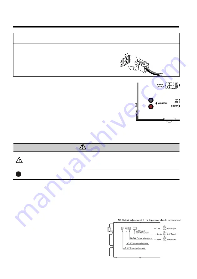
When using an external power supply


Instead of using the included AC adapter, power can be 
supplied externally. 
Connect wiring using a MOLEX connector, as shown in the figure. 
Please be sure to connect to ground. Otherwise a ground wire 
may be connected to the ground terminal on the rear of the unit. 
Please shut off the external power supply when stopping 
operation. 

Output monitor terminals 

You can easily check the AC high voltage output by connecting a digital 
multimeter or tester (1 M

 or more of impedance) to the output monitor 

terminals (MONITOR) on the side of the unit. 
(A tester pin with an outer diameter of 2 mm will fit.) 
 
1. Put the tester, etc. in AC voltage measurement mode, and connect it to 

the output monitor terminals (MONITOR). Since there is no polarity, it 
doesn't matter which side you connect to the COM terminal. 

2. Once the power is turned on for the unit, a value that is 1/1000th that 

of the AC high voltage output (AC 4 to 7 V) will be displayed on the tester. The high voltage output 
voltage will be the value which is multiplied by 1000 of the displayed value. 

    Ex.: If the tester shows 4.2 V, the high voltage output will be 4.2 kV 


CAUTIONS


CAUTIONS


• Be sure to conduct measurements with the tester in AC voltage 

measurement mode. 

• Do not apply a voltage to the output monitor terminals as it may lead 

to failure. 


REMEMBER


• Do not short the output monitor terminals or connect them to ground. 

It may lead to failure. 

Output voltage adjustment 

Make sure to carry out output adjustment 

while the ionizer is disconnected.

 When the product has 

been shipped together as a set with an ionizer, output voltage setting/adjustment has normally been 
carried out already; so this procedure is not necessary. 
After installation work is complete, double-check the output voltage by connecting a tester, etc. in AC 
voltage measurement mode to the output monitor terminals while the antistatic electrode is 
connected. Make adjustments if necessary.


AC output voltage switching


This product can switch between AC output voltages. 
Remove the top cover and operate the internal selector   
switch and adjustment knobs. 
 

Output switching (AC output selector switch)


4 kV:    Move to the left (position 1) 
5 kV:    Move to the center (position 2) 
7 kV:    Move to the right (position 3) 

<Power supply connector> 

MOLEX 5556 (pin x 2) 
MOLEX 5557-04 R (housing x 1) 

1. Power supply   
  (+24 V DC) 
4. Ground 

Summary of Contents for Stat Buster GP-1

Page 1: ...Stat Buster No GP 1 Read this instruction manual before use Keep it in a safe handy place for future reference Table of Contents For Your Safely P 2 Product Overview P 3 External View P 5 Circuit Diagram P 6 Installation P 7 Operation P 11 MEMO P 15 Troubleshooting Storage P 16 ...

Page 2: ... or don t use this product in a place where water oil solvent may be poured and or where corrosive gas such as acid alkali chlorine and so on There is a risk of electric shock and or product breakdown PROHIBITED Don t use this product in a place where a considerable shock and or vibration are given and or where a sharp temperature fluctuation or dew condensation occurs PROHIBITED Be sure to use th...

Page 3: ...hinery equipment etc connect a 24 VDC 10 1 A power supply In this case connect the 0 V side to ground Product Features AC Output Voltage Adjustment Function This power supply can adjust AC output voltage within the range of 3 5 kV to 7 kV For this reason this can be used with various VESSEL ionizers DC Output Voltage Adjustment Function This power supply can output a variable DC output voltage bet...

Page 4: ... the internal board Low voltage detection Anomaly detection function will operate when each output drops to about 85 or less of the set voltage due to high voltage short circuit or abnormal sparks Overcurrent detection the anomaly detection function will operate when the output current reaches about 4 mA or more Anomaly detection sensitivity adjustment The anomaly detection response speed can be a...

Page 5: ...5 External View ...

Page 6: ...6 Circuit Diagram ...

Page 7: ...ct uses sensitive electronic circuits so please handle it as gently as possible and avoid subjecting it to shocks etc Do not under any circumstances drill holes into the unit Please install the GP 1 near machinery to which load electrodes bars nozzles air guns etc are connected Secure firmly to a strong frame wall floor etc using 4 M5 screw through the holes in the bottom of the mounting base When...

Page 8: ...yed value Ex If the tester shows 4 2 V the high voltage output will be 4 2 kV CAUTIONS CAUTIONS Be sure to conduct measurements with the tester in AC voltage measurement mode Do not apply a voltage to the output monitor terminals as it may lead to failure REMEMBER Do not short the output monitor terminals or connect them to ground It may lead to failure Output voltage adjustment Make sure to carry...

Page 9: ...ther than the aforementioned output selector switch or output adjustment knobs Doing so may lead to accidents or malfunction The top cover is connected to the unit by a ground wire Do not remove or damage this ground wire After making adjustments be sure to put back the top cover Do not use the product without the top cover Anomaly Detection Circuit For safety the anomaly detection circuit automat...

Page 10: ...ector varies depending on the type of ionizer The maximum load that can be connected to this product in the case of the SSB bar series ionizer is a bar with a total overall length of 5 m Details about our other ionizers can be found in the instruction manual for each model Using this product with loads in excess of the maximum load radically shortens the life of the unit electrode and high voltage...

Page 11: ...etc shows approximately 0 V 〇 High voltage output is stopped and static elimination ceases Anomaly detection If sparks occur or if there is a high voltage short circuit etc resulting from an anomaly in the high voltage cable electrode or power transformer high voltage output will be turned OFF and the power indicator light will go out 〇 Power indicator light goes out 〇 Error alarm output contacts ...

Page 12: ...e adjusted There is an adjustment knob on the other side of the connectors Turning the knob labeled ION BALANCE ADJ to the left or right increases or decreases the DC voltage adjusting the amount of positive and negative ions produced by the ionizer Carry out adjustments by measuring the actual ion balance with a CPM charged plate monitor etc IF THE PRODUCT HAS BEEN PURCHASED AS A SET WITH AN IONI...

Page 13: ...l is coming from the unit The unit is considerably distorted The unit is abnormally hot enough that it cannot be touched with bare hands It is making an unusual humming sound which can be easily heard from 1 m away The power indicator light does not come on even though the power switch is turned to ON CAUTION PROHIBITED Do not use the product in the following conditions Risk of fire or electric sh...

Page 14: ...ried out for capacitive coupling type antistatic electrode The anomaly detection circuit operates and stops output Bad ground Inspect each ground The load is too great Decrease the load Reduce the number of electrodes or shorten the length of the high voltage cable The electrode and insulation of the ionizer are extremely dirty Clean or replace the electrode needles etc Failure of the electrode or...

Page 15: ...15 MEMO ...

Page 16: ... neglect misuse alterations operator error or failure to properly maintain clean or repair products LIMIT OF LIABILITY This electronic static eraser use high voltage corona discharge and should not be used in or near flammable or explosive environments In no event will VESSEL or any seller is responsible or liable for any injury loss or damage direct or consequential whether based in tort or contr...

Reviews: