10
10
3
A
Initial physical setup and connections
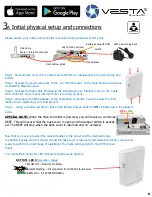
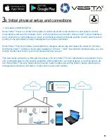
Please ensure your Vesta main controller is powered and operational at this point.
VESTA Main Controller
Main home
Router / Internet Connection
Data cable supplied
VESTA Power Plug Pack
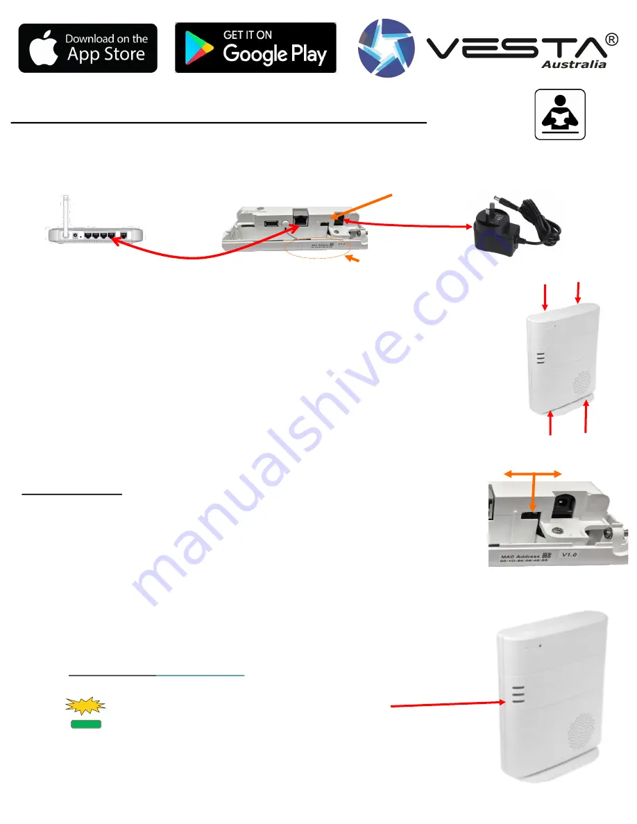
Step 1. Remove back cover of the Vesta main controller by unscrewing the four screws top and
bottom.
Step 2. Connect the power plug pack to the 12 volts DC socket on the main Vesta Controller as
illustrated in diagram above.
Step 3. Connect the Data cable Provided in the kit between your Internet router to the Vesta
Main Controller. Be sure your internet router is working properly.
Step 4. Write down the MAC Address of the Vesta Main Controller. You will require this infor-
mation when registering your cloud account.
Step 5 . Using a small screw driver, flick on the Battery backup switch to
ON
as illustrated in the diagram
below
.
SPECIAL NOTE:
When the Main controller is powered, you will receive a continues
BEEP. This will occur whilst the back cover is open and the tamper switch is activat-
ed. The BEEP will stop when the back cover is returned and re–
screwed.
Now that you have connected the relevant cables to the power and the internet/Router,
the battery backup switch is turned on and the back cover is returned and screwed correctly, you are now
ready to perform the next stage of registration the Vesta alarm system to the VESTA Cloud
Portal.
Your Vesta Main Controller LED Indicator should now be flashing
Mac Address
Battery backup OFF/ON
Switch
OFF
-
ON
BOTTOM LED 3
(Operation Status)
YELLOW ON = Network Problems
YELLOW Flashing = Disconnected from VESTA Cloud Server
GREEN ON = All SYSTEM NORMAL
8


