6
6
2
A
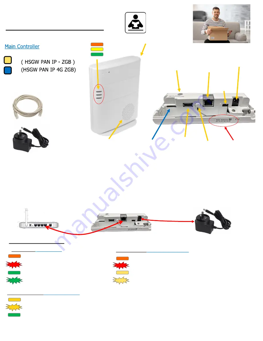
Unpack all the parts
Tamper switch
Internet
connection
4G Sim Slot GSM
Z
-
Wave USB
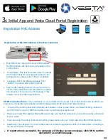
MAC Address
Default Reset
12Volt Plug Pack
Internet lead x 1
12 Volts DC Plug Pack
Internal Siren
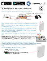
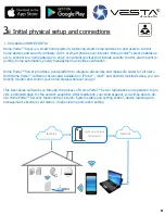
Unpack the kit content on a table. Remove the mounting back plate from the control unit by unscrewing the two
bottom screws and top screws. Open back plate from Main Controller unit to expose the connections as illustrated in
the diagrams above. A power adaptor is supplied that plugs into the main wall socket and control unit. Plug in the
power adaptor and connect the box to your internet router using the cable provide. In addition to the power
adapter, there is a rechargeable battery inside the control unit that serves as a backup in case of a power
failure. A fully charged battery can provide backup power for a period of at least 10 hours. It takes approximately
72 hours fully charge the battery.
LED Indicators
LED Indicators
Control Unit
TOP LED 1
(
Panel Status)
RED = Solid ON : Alarm is ARM
RED = Flashing : Home is ARM
GREEN = Solid ON : Alarm Disarm
GREEN = Flashing : Learning Mode
Middle LED 2
(Alarm & Fault Status)
RED = Alarm been Triggered
RED = Flashing On going Alarm Event
YELLOW = DEVICE Fault Temper / LOW Battery
YELLOW
-
Flashing = Mains power Failed
BOTTOM LED 3
(Operation Status)
YELLOW ON = Network Problems
YELLOW Flashing = Disconnected from VESTA Cloud Server
GREEN ON = All SYSTEM NORMAL
VESTA Main Controller
Main home
Router / Internet Connection
Data cable supplied
VESTA Power Plug Pack
Battery
backup
switch
4


