background image

5

The Rotational Bracket has an adjustable head which can be attached to the IR Remote Control. After 
installing the bracket on the wall, the user can adjust the angle of the head to change the direction IR 
Remote Control is facing.   

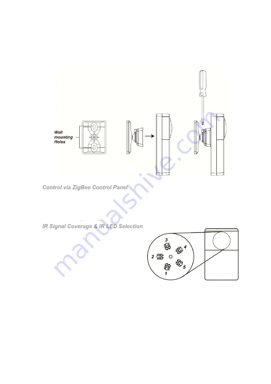
1. The Rotational Bracket base has 2 mounting holes, Use the holes as template to drill holes in the wall,

insert wall plugs if required.

2. Screw the bracket onto the wall.
3. Hook the IR Remote Control onto the brackets using the holes on the back.
4. After completing installation, you can use a Philip screw driver to loosen the screw on top of the bracket,

then adjust the IR transmitter angle and tighten the screw to lock the bracket angle.

Operation 

Control via ZigBee Control Panel

The IR Remote Control can be controlled via 

Vesta

 ZigBee Control Panels remotely to transmit IR signal.

Selecting the appliance type and IR signal number from the Control Panel will control the IR Remote 
Control to send IR signal accordingly. 

Example:  

a. Select “Air Conditioner Function 1” will control the IR Remote Control to send IR signal 1 learnt in Air

Conditioner appliance type.

IR Signal Coverage & IR LED Selection

The IR Eye of the IR Remote Control includes 6 LEDs
which are used to transmit IR signals, with 1 central 
LED and 5 surrounding LEDs. The 5 surrounding 
LEDs are positioned at 45

°

 angle to the PCB board. 

LED Signal Coverage:


Each LED transmits IR signal in cone coverage in front 
of the LED. The LEDs can be selected to transmit 
signal for each appliance type by using your Gateway. 

Example:  

a. If you select LED 1 for Air Conditioner, the IR

Remote Control will transmit signal with both
Central LED and LED 1 when it transmits an Air Conditioner appliance type IR Signal.

b.

If you select LED 2 and LED 3 for Home Audio, the IR Remote Control will transmit signal with
both LED 2 and LED 3 when it transmits a Home Audio appliance type IR Signal.

When installing the IR Remote Control, select the IR LED used via your Control Panel according to the IR 
Remote Control mounting location to allow IR transmitter to send signal to all appliance in your home. 
Please refer to your 

Vesta

 Control Panel manual for more information on IR Remote Control setting and 

control. 
Please refer to diagram below for IR signal coverage: 

Summary of Contents for UPIC-5 ZBS

Page 1: ...smits IR signal to appliances 2 ZigBee Button 3 IR Button 4 ZigBee LED Flashes twice IR Remote Control successfully joins ZigBee network Flashes every 20 minutes IR Remote Control has lost connection to its current ZigBee network 5 IR Indicator LED Slow Flash IR Remote Control under IR learning mode Quick Flash IR Remote Control receives IR signal under learning mode or is transmitting IR signal F...

Page 2: ... Remote Control can only join ZigBee network within 3 minutes after power on 1 Insert batteries to power on the IR Remote Control 2 Within 3 minutes press and hold the ZigBee button for 10 seconds then release it to join the network Please make sure the permit join feature on the router or coordinator of your ZigBee network is enabled 3 After joining the ZigBee network the IR Remote Control will b...

Page 3: ...thers Fan X means the location of this switch has no effect on appliance selection Example a To select Air Conditioner slide Switch 1 to ON and Switch 2 6 to OFF b To select Television slide Switch 2 to ON and Switch 3 6 to OFF ignore Switch 1 position Step 3 Learn IR Data Each appliance type can learn up to 8 IR signals selected with Dip Switch Set 2 Switch 1 Switch 2 Switch 3 Switch 4 Switch 5 S...

Page 4: ...Switch 3 Switch 4 Switch 5 Switch 6 Appliance Selection ON OFF OFF OFF OFF OFF Type 1 Air Conditioner OFF ON OFF OFF OFF OFF Type 2 Television OFF OFF ON OFF OFF OFF Type 3 Home Audio OFF OFF OFF ON OFF OFF Type 4 Set Top Box OFF OFF OFF OFF ON OFF Type 5 Others Fan Slide more than one switch to ON will select multiple appliance type Example a Slide Switch 1 2 3 4 5 to ON will select all 5 applian...

Page 5: ... Remote Control to send IR signal 1 learnt in Air Conditioner appliance type IR Signal Coverage IR LED Selection The IR Eye of the IR Remote Control includes 6 LEDs which are used to transmit IR signals with 1 central LED and 5 surrounding LEDs The 5 surrounding LEDs are positioned at 45 angle to the PCB board LED Signal Coverage Each LED transmits IR signal in cone coverage in front of the LED Th...

Page 6: ...on Power Use the jumper switches JP2 and JP3 to adjust the IR signal transmission power Factory default is set to Low transmission power JP1 ON Setting the jumper to JP2 will increase the IR signal transmission range ...

Page 7: ...ng 0 32 bytes Read Write O 0x0011 PhysicalEnvironment 8 bit 0x00 0xff Read Write 0x00 O 0x0012 DeviceEnabled Boolean 0x00 0x01 Read Write 0x01 M Attribute of Power CFG Cluster Information Identifier Name Type Range Access Default Mandatory Optional 0x0035 BatteryAlarmMask map8 0b0000 000x Read Write 0x00 0 Attribute of Identify Cluster Information Identifier Name Type Range Access Default Mandator...

Page 8: ...isable For example 20 100000 in Bit number meaning that only LED 6 The central LED will be activated when UPIC transmit IR signal in this appliance type If you want to set the IR signal to be transmitted with both LED 2 and LED 6 the value in bit number will be 0010 0010 0x22 0 0 1 0 0 0 1 0 Reserved Reserved LED 6 Enable LED 5 Disable LED 4 Disable LED 3 Disable LED 2 Enable LED 1 Disable 0010 00...

Reviews: