background image

27

Installing a Vent

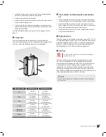
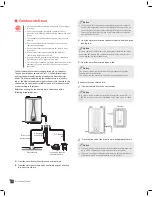
Connecting the Vent Clip

Caution

To connect the exhaust vent firmly, must use the vent clip 

included with water heater.

To connect the vent clip:

1

Connect the vent clip to the exhaust vent.

2

Connect the exhaust vent and the vent clip to the flue 

connector.

Vent Termination

Caution


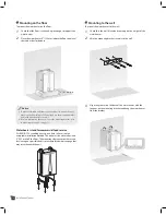
Air intake must be protected from any debris.


When connecting the air intake connector and the flue 

connector with the vent, connecting parts must be sealed 

with PVC, glue and high temp silicon.


Maintain 12" (300 mm) min. (18" (450 mm) min. for Canada) 

clearance above highest-anticipated snow level. Maximum 

of 24" (600 mm) above roof.


Install a bird screen at the end of the intake air pipe.

Determine what type of vent termination is appropriate for the 

installation location and situation before installing the water heater. 

The following subsections describe some venting configurations, 

but do not include all possible options.

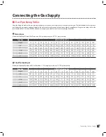
  Single-pipe sidewall venting

3

Schedule 40 PVC Pipe

10" (254 mm) min.

12" (300 mm) min.

Caution


Maintain 12" (300 mm) min. (18" (450 mm) min. for Canada) 

clearance above highest-anticipated snow level. Maximum 

of 24" (600 mm) above roof.


Install a bird screen at the end of the intake air pipe.

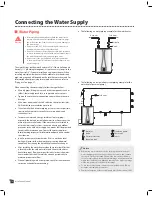
Notice

Single-pipe venting requires that adequate combustion air be provided 

in end-use installations per NFPA 54 C.9.3.2.

Summary of Contents for VH-150

Page 1: ...ensed professional must install the water heater according to the exact instructions of the manual Warning If the information in these instructions is not followed exactly fire or explosion may result causing property damage personal injury or death Do not store or use gasoline or other flammable vapors and liquids in the vicinity of this or any other appliance What to do if you smell gas Do not t...

Page 2: ...oom or area as the water heater Vapors from flammable liquids can explode and or catch fire causing death or severe burns Keep flammable products far away from the water heater and store them in approved containers Keep the containers tightly closed and out of the reach of children The Water heater has a main burner flame that can come on at any time and will ignite flammable vapors Vapors cannot ...

Page 3: ...not operate the water heater without proper venting Failure to do so may result in fire or carbon monoxide CO poisoning which may result in property damage personal injury or death Caution Do not use the water heater for anything other than its intended purpose as described in this manual Failure to do so may result in property damage personal injury or death Do not turn on the water heater unless...

Page 4: ...rade directly in line with the exhaust vent terminal for the horizontally vented gas fuelled heating appliance or equipment The sign shall read in print size no less than one half 1 2 inch in size GAS VENT DIRECTLY BELOW KEEP CLEAR OF ALL OBSTRUCTIONS 4 INSPECTION The state or local gas inspector of the side wall horizontally vented gas fuelled equipment shall not approve the installation unless u...

Page 5: ...y 15 Gas Pipe Sizing Tables 15 Gas Piping 16 Inlet Gas Pressure 17 Connecting the Water Supply 18 Water Piping 18 Pressure Relief Valve 19 Condensate Drain 20 Condensate Trap 21 Installing a Vent 22 Vent Type 22 Vent Pipe Materials 26 Vent Length 26 Connecting the Vent Clip 27 Vent Termination 27 Setting the DIP Switches for Cascade System 30 Connecting the Power Supply 31 Self adjusting Mode 32 I...

Page 6: ...it Vent clip Cascade communication cable Notice If there is a missing item please contact Technical Support at 1 800 761 0053 Optional Accessories The following optional accessories are not included with the water heater but may be necessary for the installation Check the need for any of the following optional accessories before installation Pressure relief valve Remote controller Plumb easy valve...

Page 7: ...oor wall hung or stand Venting Type Forced draft direct vent Ignition Electronic ignition Water Pressure Max 150 psi Natural Gas Supply Pressure 3 5 10 5 WC Propane Gas Supply Pressure 8 13 WC Natural Gas Manifold Pressure Max Min 0 02 WC 0 15 WC 0 02 WC 0 25 WC Propane Gas Manifold Pressure Max Min 0 01 WC 0 1 WC 0 01 WC 0 15 WC Reserve Tank 3 Gallons 11 Liters Minimum Flow Rate 0 GPM Connection ...

Page 8: ...lectrical supply available in the installation location If the water heater does not match each of these ratings do not install the water heater If the gas conversion is required the included gas conversion kit must be used VESTA DS INC 2711 LBJ Freeway Suite 320 Farmers Branch Texas75234 1 800 761 0053 16 6 Chauffe eau Automatique Instantan Ventilation Directe 0 6 L 6 inchs R and not suitable NG ...

Page 9: ... water inlet 3 4 E Pressure relief valve connector 3 4 F Drain valve 3 4 G Condensate outlet 3 4 H Gas inlet 3 4 A B C D 12 30 312 6 mm 6 89 175 mm 13 6 345 mm 3 43 87 1 mm 11 58 294 2 mm 18 11 460 mm E F H G 27 56 700 mm 9 59 243 6 mm 5 83 148 1 mm 2 20 55 7 mm 1 80 45 6 mm 4 30 109 1 mm 2 22 56 5 mm 3 27 83 mm 31 08 789 5 mm ...

Page 10: ...ake connector Cold water block Surge pressure regulation valve Low water cut off switch Flow control valve Condensate trap Rubber feet Air pressure switch PCB assembly Air intake hose Over heat preventer Tank heat exchanger assembly Power Cable Mixing valve ...

Page 11: ...11 General Information Hot water outlet Cold water inlet Drain valve Turbo fan assembly Surge pressure regulation valve Pressure relief valve connector Front panel Gas pipe Gas valve Duct assembly ...

Page 12: ...water meets EPA quality standards The following table shows the maximum contaminant levels allowed based on the EPA National Secondary Drinking Water Regulations 40 CFR Part 143 3 If you suspect that your water is contaminated in any way stop using the water heater and contact an authorized technician or licensed professional Contaminant Maximum Allowable Level Total Hardness 200 mg l 12 grains ga...

Page 13: ...nd debris may accumulate or where combustion air can be contaminated Do not install the water heater in areas with greasy fumes or heavy amounts of steam if necessary take measures to prevent fumes and steam from entering the water heater Chemicals that are corrosive in nature should not be stored or used near the water heater High elevation The water heater can be installed at elevations under 4 ...

Page 14: ...ket refer to Mounting to the wall on page 14 Water heater stand for commercial food service Per ANSI NSF 5 standing directly on a hard surface is not an acceptable installation method The unit must be elevated at least 6 152 mm off the floor This mounting clearance provides access for clearing any possible debris or accumulated water seepage that may occur beneath the unit Mounting to the wall To ...

Page 15: ...40 50 60 70 80 90 100 125 150 200 3 4 372 255 205 175 156 142 130 121 114 107 95 86 74 1 702 482 387 331 293 266 245 228 213 202 179 162 139 1 1 4 1441 990 795 680 603 546 503 468 439 415 367 332 285 1 1 2 2158 1483 1191 1019 903 819 753 701 658 621 550 499 427 2 4155 2856 2293 1963 1740 1576 1450 1349 1266 1195 1060 960 822 Liquid propane gas Maximum Capacity of propane LP Gas Based on 11 WC supp...

Page 16: ...irst appliance to be connected to the gas supply line To connect the gas supply 1 Determine the gas type and pressure by referring to the rating plate 2 Perform a pressure test on the main gas supply line 3 Purge the gas line of any debris 4 Determine the proper type and size for the gas line Refer to the gas pipe sizing tables on page 15 5 Install a union 6 Install a manual gas shut off valve on ...

Page 17: ...e To measure the inlet gas pressure 1 Open a hot water faucet The water heater should turn on and the gas in the gas supply line will be purged 2 Leave the faucet on until the water heater shuts down due to a lack of gas supply and then turn off the hot water faucet 3 Remove the water heater front cover by loosening the 2 Phillips screws securing it to the case 1 1 2 2 4 Loosen the screw indicated...

Page 18: ...te all water piping especially the hot and recirculation water lines Never cover the drain or pressure relief valve If the water heater is installed in a closed water supply system such as one having a backflow preventer in the cold water supply line means shall be provided to control thermal expansion Contact the water supplier or local plumbing inspector for information about how to control this...

Page 19: ...ure relief valve on the pressure relief valve connector Pressure relief valve Notice In recirculating system install the pressure relief valve on the hot water outlet The pressure relief valve should be placed as close to the water heater as possible No other valve should be placed between the pressure relief valve and the water heater When installing the valve follow these guidelines Ensure that ...

Page 20: ...er To a laundry tub To a laundry tub via a condensate pump A From the water heater directly into an external drain B From the water heater through a neutralizing agent and then into an external drain Notice If you choose this option the neutralizing agent must be replaced periodically Depletion of the neutralizing agent will vary based on the usage rate of the water heater During the first year of...

Page 21: ...ugh the flue connector The water heater may be severely damaged unless filled with water prior to operation Pour 0 1 gallon 400 ml of water into the exhaust duct Deflate air sufficiently or equip the air vent with an outlet pipe prior to filling the condensate trap with water there must be no air inside the heat exchanger ...

Page 22: ...er of elbows and distances to air intake are observed Do not store hazardous or flammable substances near the vent termination If this water heater is to be installed in an area where snow is known to accumulate protect the vent termination from blockage Ensure that the vent termination is at least 12 305mm above ground or as required by local codes Support the vent pipe with hangers at regular in...

Page 23: ...al air supply inlet to building or the combustion air inlet to any other application 36 in 91 cm 12 in 30 cm K Clearance to mechanical air supply inlet 72 in 182 cm 36 in 91 cm above if within 10 feet horizontally L Clearance above paved sidewalk or paved driveway located on public property 84 in 236 cm 3 M Clearance under veranda porch deck or balcony 12 in 30 cm 4 1 In accordance with the curren...

Page 24: ...ion use a direct venting system for the water heater When installed in a manufactured home mobile home all combustion air must be supplied from the outdoors as described on page 26 When using non direct venting maintain non direct vent clearances shown on page 29 as required by ANSI Z21 10 3 and the National Fuel Gas Code ANSI Z223 1 NFPA 54 and CAN CSA B149 1 Natural Gas and Propane Installation ...

Page 25: ... supply inlet to building or the combustion air inlet to any other application 36 in 91 cm 4 feet below or to side of opening 1 foot above opening K Clearance to mechanical air supply inlet 72 in 182 cm 36 in 91 cm above if within 10 feet horizontally L Clearance above paved sidewalk or paved driveway located on public property 84 in 236 cm 3 84 in 236 cm M Clearance under veranda porch deck or ba...

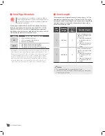
Page 26: ...ust not be interchanged with other vent systems or unlisted pipes or fittings All plastic components and specified primers and glues of the certified vent system must be from a single system manufacturer and must not be intermixed with another system manufacturer s parts The supplied vent connector and vent termination are certified as part of the water heater Vent Length The maximum vent length w...

Page 27: ...ove highest anticipated snow level Maximum of 24 600 mm above roof Install a bird screen at the end of the intake air pipe Determine what type of vent termination is appropriate for the installation location and situation before installing the water heater The following subsections describe some venting configurations but do not include all possible options Single pipe sidewall venting 3 Schedule ...

Page 28: ... Maximum of 24 600 mm above roof Install a bird screen at the end of the intake air pipe Notice It is recommended to install the intake air vent terminal as far from the exhaust gas vent terminal as possible Snorkel flue 10 254 mm min 12 300 mm min 12 300 mm min Schedule 40 PVC pipe Caution Maintain 12 300 mm min 18 450 mm min for Canada clearance above highest anticipated snow level Maximum of 24...

Page 29: ... Maintain 12 300 mm min 18 450 mm min for Canada clearance above highest anticipated snow level Maximum of 24 600 mm above roof Two pipe vertical venting 36 900 mm min Exhaust gas 12 300 mm min From any obstruction above below left or right Intake air 12 300 mm min Caution Maintain 12 300 mm min 18 450 mm min for Canada clearance above highest anticipated snow level Maximum of 24 600 mm above roof...

Page 30: ... 4 ON Minimum heat capacity operation 1 2 3 4 ON Maximum heat capacity operation 3 switch panel Switch Function 1 2 3 ON One water heater is in use 1 2 3 ON Two water heaters are in use for the cascade system 1 2 3 ON Three water heaters are in use for the cascade system 1 2 3 ON Four water heaters are in use for the cascade system 1 2 3 ON Five water heaters are in use for the cascade system 1 2 ...

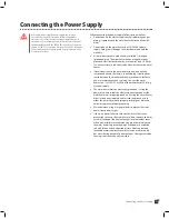
Page 31: ...If local codes require the water heater to be wired directly remove and discard the factory installed plug Install a power switch between the breaker and the water heater to facilitate end user maintenance and servicing Connect the water heater to a 110 120V AC at 60 Hz with a maximum of 5A rating electrical supply The water heater must be electrically grounded If using the power plug ensure that ...

Page 32: ...ion circumstances altitude vent and self adjust the heat capacity by itself To use the Self adjusting Mode 1 Connect the power supply 2 Press the button 3 Open more than two faucets and dispense approximately 4 gallons 15 liters of water 4 Check that the icon is turned on Notice Temperature is set to 120 F 50 C by default 5 Touch the button and increase the temperature higher than 160 F 71 C 6 Tou...

Page 33: ...ore than 5 seconds CAL1 appears on the digital display and start flashing 8 CAL 1 flashes for about 6 minutes When CAL1 is flashing it means the heat capacity is adjusting 9 After the heat capacity adjustment is finished CAL1 disappears from the digital display Close all faucets ...

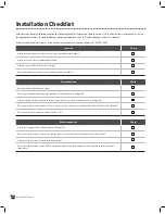
Page 34: ...ntenance clearances Gas connection Check Have you tested all the fittings for leaks Does the gas supply match the gas type specified on the water heater s rating plate Is the gas supply pressure adequate as the gas supply pressure specified in the water heater s rating plate Does the installation conform with local codes or in the absence of local codes the National Fuel Gas Code ANSI Z223 1 NFPA ...

Page 35: ...e all vent runs properly supported Is the vent termination properly supported Have you explained to the owner importance that vent termination not be blocked Have you run the Self adjusting Mode if you installed the water heater in a location higher than 4500 ft Others Check Is the front panel working properly Have you filled the condensate trap with fresh water Have you explained how to operate t...

Page 36: ...installation of this kit The installation is not proper and complete until the operation of the converted appliance is checked as specified in the manufacturer s instructions supplied with the kit A qualified service agency is any individual firm corporation or company which either in person or through a representative is engaged in and is responsible for the connection utilization repair or servi...

Page 37: ...ling a cascade system carefully consider the design of the system and the features of the installation location Follow all local codes and regulations as well as all guidelines for installing the water heater The following sections describe additional considerations that are specific to installing a cascade system Read the following sections carefully before designing or installing the system Pipi...

Page 38: ...ch water heater is 2 GPM Communication cables Caution To avoid electric shock turn off the water heater while connecting the wires Up to 8 water heaters can be connected with cascade communication cables To connect the cascade communication cables 1 Connect the cascade communication cable connector to the connector socket on the PCB assembly Red Green 2 Remove the plastic insulation from opposite ...

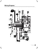
Page 39: ...Bypass Control Valve Ground Heat Exchanger Thermistor OUTLET Thermistor INLET Thermistor Exhaust Thermistor Black White BROWN GRAY ORANGE BLUE YELLOW PURPLE RED BLACK BROWN GRAY ORANGE BLUE YELLOW PURPLE RED BLACK BROWN GRAY ORANGE BLUE YELLOW PURPLE RED BLACK BROWN GRAY ORANGE BLUE YELLOW PURPLE RED BLACK Ground Id1 Id2 Id3 MIN MAX PRG LONG HB OPTION CASCADE SYSTEM Yellow White Black Red Brown Wh...

Page 40: ...ponent Assembly Diagrams and Parts Lists Case Parts 123 120 130 129 113 112 127 111 110 101 126 126 126 126 128 128 106 105 113 124 125 128 128 102 118 103 108 104 109 128 114 128 107 128 122 127 117 116 119 116 121 127 115 116 ...

Page 41: ...11 3040604 Air Intake Filter 112 3080290 Saddle 113 3040576 Handle 114 3030227 Outlet Nipple 115 3040602 Air Intake Connector 116 3080235 Flue Packing 117 3120139 Reducer Pin 118 3100044 M4x12 Screw 119 3040603 Flue Connector 120 3130750 Hot Water Outlet Temperature Sensor 121 3040687 Flue Connector Reducer 122 3030246 Inlet Nipple 123 3120136 Inlet Nipple Filter 124 2060356 Drain Valve 125 304057...

Page 42: ...llation Manual Flue Parts 231 227 230 229 204 228 203 236 220 225 219 215 235 213 214 222 221 216 207 205 205 212 206 235 232 237 233 235 224 202 208 128 209 210 211 238 201 235 217 223 128 226 218 234 239 235 ...

Page 43: ...2 Flam View Pipe Gasket 217 2020407 Flame Rod 218 3090362 Flame Rod Gasket 219 3050101 Fan Connector 220 3080220 Fan Connector O Ring 221 3050100 Fan Adapter 222 3011393 Burner Plate 223 3080223 Condensate Hose 224 2060375 Condensate Silicone Hose 225 3090373 Fan Connector Gasket 226 2060339 Condensate Trap Assembly 227 3100176 M4 Nut 228 3090361 Burner Gasket 229 3090341 Ceramics Board 230 301157...

Page 44: ...nstallation Manual Water Parts 304 305 306 212 212 307 212 212 310 311 309 313 319 212 316 210 212 212 318 212 124 320 321 323 301 302 212 303 308 314 312 212 324 319 237 322 128 311 317 212 315 238 212 212 ...

Page 45: ...g Pipe 309 3030251 Clod Water Inlet 3Way Nipple 310 2060344 Check Valve 311 3080043 1 2 Packing 312 2091120 Water Inlet Elbow Pipe 313 2091121 By Pass Pipe 314 2060357 Surge Pressure Regulation Valve 315 3030253 Cold Water Block 316 2091093 Flow Control Valve Inlet Pipe 317 2060262 Flow Control Valve 318 3030252 Tank Inlet Nipple 319 3080277 P18 O Ring 320 2091036 Drain Pipe 321 2060338 Low Water ...

Page 46: ...Memo ...

Page 47: ...Memo ...

Page 48: ...Address 2711 LBJ Fwy Suite 320 Farmers branch TX 75234 For Technical Support 1 800 761 0053 www vestahws com Ver 1 0 ...

Reviews: