Notes for professional electricians
Installation and start-up:
1. Switch off the power supply.
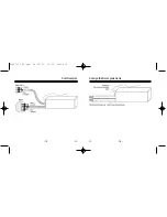
2. Connect the cables according to the wiring diagram (see page 31).
Attention: Currently valid VDE standards must be observed
when connecting the device, in particular DIN VDE
0100/0700 as well as the currently valid regulations
of your local power company and accident preven-
tion regulations.
3. Mount the device in a suitable location using the installation equip-
ment.
4. Switch on the power supply and check if the red LED on the front
side of the device is flashing.
5. Program the buttons of the radio transmitter (see page 27). Make
sure to program retract and extend button separately.
6. Press the retract and extend button to check if the rotational direc-
tion of the motor corresponds with the direction buttons. If not,
exchange the brown with the black wire of the motor connection
cable.
G
- 25 -
Notes for professional electricians
Important: Parallel control of several drive motors with a
Vestamatic
VestaFunk MS 16
can only be implemented by means of
isolating relays.
When operating several
Vestamatic
VestaFunk MS 16
radio transmitters, a minimum distance of 30 cm must be
observed between the individual radio transmitters.
The following suitable radio transmitters are available:
Hand-held radio transmitter 2-channel, article-no. 01097010
Hand-held radio transmitter 4-channel, article-no. 01097110
Wall-mounted radio transmitter 4-channel, article-no. 01099010
When controlling 2 drives, please use our:
Isolating relay TR N2A,
article-no. 01054120.
G
- 26 -
83201911 H1.qxd 04.04.01 11:20 Seite 25


