background image


Item no.: 960314.R5 


Date 2006-09-11 

Issued by: Technology 


Class: II 

Type: MAN 


Page 12 of 32 


Safety Regulations for Operators and Technicians 

V90 – 3.0MW/V100 – 2.75MW 


Vestas Wind Systems A/S · Alsvej 21 · 8900 Randers · Denmark · www.vestas.com 
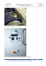
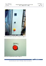
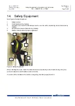
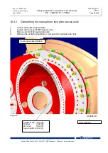
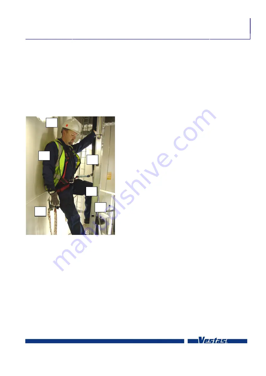
 

14. Safety 

Equipment 

See Figure 2 Safety Equipment 
 
1. Safety 

helmet. 

2. 

H-belt (delivered by Vestas). 

3. 

Lanyards: one line with a fall damper device, one line with a shortening device (delivered by 
Vestas). 

4. 

Fall protection device (delivered by Vestas). 

5. 

Rubber-soled footwear properly tightened. 


Figure 2 Safety Equipment 
 
When climbing the tower, fasten the fall protection device directly to the H-belt's D-ring. Only one 
person is allowed on each ladder section at a time. 
 
If a service lift is installed in the turbine, bring along the safety equipment in it. 

Summary of Contents for V100-2.75MW

Page 1: ...may dictate more extensive setbacks in no event shall such decision decrease the number of turbines below 13 or decrease the aggregate wind efficiency of the project as presented by by the applicant a...

Page 2: ...and accidents rarely happen is not an acceptable way of thinking Most of us drive airbag equipped cars The reason we have airbags is because they are proven to reduce injury and they are there if we...

Page 3: ...630464 5 APPENDIX O OPERATION AND MAINTENANCE PLAN...

Page 4: ...Vestas Wind Systems A S Alsvej 21 8900 Randers Denmark www vestas com Class II Item no 964106 R00 2007 06 29 Mechanical Operating and Maintenance Manual V90 3 0 MW VCRS 60 Hz Onshore Offshore Mk 7...

Page 5: ...ce Manual History of this Document Vestas Wind Systems A S Alsvej 21 8900 Randers Denmark www vestas com History of this Document Rev no Date Description of changes 00 2007 06 29 First edition Table o...

Page 6: ...73 User Guide Do not hesitate to contact your plant manager or Vestas Service Department if you need more detailed explanations Vestas Wind Systems A S Alsvej 21 DK 8900 Randers Telephone 45 9730 0000...

Page 7: ...stem 9 950270 Composite Coupling 10 963244 Gear Oil Lubrication System 11 958534 Generator and Transformer 12 958612 Yaw Gear 13 960304 Yaw Bearing System 14 958614 Hydraulic System 15 958636 Wind Sen...

Page 8: ...Date Description of change 0 2005 06 23 First edition 1 2005 09 19 947554 replaced by 959055 Chap 9 However the capacitors in the converter and AGO2 section might be energized inserted Chapter 10 Con...

Page 9: ...p F60 8 5 2 Lift Optional 8 5 3 Internal Crane 8 6 Practical Advice at Inspection 8 7 Influence by Lubricants 8 8 High Voltage Installations 8 9 Grid Drop Out 9 10 Converter and AGO2 Sections 9 11 Tur...

Page 10: ...ed in situations where measurement and work is done in junction boxes that can be connected to power Consequently the following safety regulations must be observed 2 Stay and Traffic by the Turbine Do...

Page 11: ...ons of emergency stop buttons and trip F60 in nacelle at Ground controller at the bottom of the turbine Gearbox pos 1 Yaw ring pos 2 Nose cone pos 3 only local stopping function Nacelle controller pos...

Page 12: ...0 Randers Denmark www vestas com Remember The hydraulic system is still under pressure Due to the accumulators up to 6 litres of hot oil will pour out if the hydraulic system is intervened Please note...

Page 13: ...ge 6 of 32 Safety Regulations for Operators and Technicians V90 3 0MW V100 2 75MW Vestas Wind Systems A S Alsvej 21 8900 Randers Denmark www vestas com Picture 3 Gearbox emergency stop button pos 1 Fi...

Page 14: ...Type MAN Page 7 of 32 Safety Regulations for Operators and Technicians V90 3 0MW V100 2 75MW Vestas Wind Systems A S Alsvej 21 8900 Randers Denmark www vestas com Picture 5 Emergency stop button in h...

Page 15: ...ely for oil spills and loose bolts Dirt must be wiped off otherwise it can be difficult to determine whether there is a significant leak Loose bolts in the structure mean danger They must be tightened...

Page 16: ...ion from the grid Switch Q7 and Q8 must be turned off Before opening the cabinet check the DC link voltage in picture 17 Before working on the converter AGO2 check the DC link voltage with a Fluke mul...

Page 17: ...rap MUST be mounted Do not mount the fall protection hook on the aluminium ladder rungs or on the fittings for the ladder as they might brake in case of falling Instead the swivel eye plate yellow mus...

Page 18: ...the nacelle while the turbine is in operation unless if checking for gear and generator noise Any oil or grease spills must be cleaned up because of the risk of slipping Make sure that the covering a...

Page 19: ...t 2 H belt delivered by Vestas 3 Lanyards one line with a fall damper device one line with a shortening device delivered by Vestas 4 Fall protection device delivered by Vestas 5 Rubber soled footwear...

Page 20: ...e tower should be cut off by fire or other unforeseen events a rescue and descent device is located in the nacelle behind the main controller section in an aluminium box Please see user manual for res...

Page 21: ...tions for Operators and Technicians V90 3 0MW V100 2 75MW Vestas Wind Systems A S Alsvej 21 8900 Randers Denmark www vestas com 14 2 Access to Roof Place the ladder on machine foundation at the rear o...

Page 22: ...MW V100 2 75MW Vestas Wind Systems A S Alsvej 21 8900 Randers Denmark www vestas com 15 Hooking Points and Safety Chains A number of hooking points is installed at different locations in the nacelle A...

Page 23: ...Page 16 of 32 Safety Regulations for Operators and Technicians V90 3 0MW V100 2 75MW Vestas Wind Systems A S Alsvej 21 8900 Randers Denmark www vestas com Picture 10 Safety chains must be mounted when...

Page 24: ...a CO2 extinguisher in a closed room can result in lack of oxygen 17 Directions for Use of Rotor Lock To avoid accidents and near accidents which can be prevented via mechanical locking of the rotor th...

Page 25: ...s involves a disassembly of mechanical parts b yaw brakes cannot be activated 6 Work on electricity in the nacelle if this involves a that the turbine controller is switched off and work at rotating p...

Page 26: ...blade may be pitched at a time The rotor locking system is located at the upper right hand side of the main gear see Picture 12 Rotor locking system 1 Set the turbine to PAUSE mode and select test pic...

Page 27: ...32 Safety Regulations for Operators and Technicians V90 3 0MW V100 2 75MW Vestas Wind Systems A S Alsvej 21 8900 Randers Denmark www vestas com Picture 12 Rotor locking system Picture 13 Alignment ma...

Page 28: ...earbox replacements Transport of nacelle Turbine standstill for long period of time 48 hours The manual rotor lock must be used as an alternative to the hydraulic rotor lock The following components m...

Page 29: ...he hub flange and into the locking holes of the main foundation 3 Place 16 x M42 bolts 782139 5 on each side and 6 in the top 4 Insert 16 shims 782142 so the bolt is placed in the slot and the shims U...

Page 30: ...I Type MAN Page 23 of 32 Safety Regulations for Operators and Technicians V90 3 0MW V100 2 75MW Vestas Wind Systems A S Alsvej 21 8900 Randers Denmark www vestas com Do not at any time remove the cent...

Page 31: ...ders Denmark www vestas com 18 2 2 Dismantling the manual rotor lock after service work 1 Loosen all the M16 special bolts 2 Loosen and remove all M42 special nuts 3 Remove all the M42 special pin bol...

Page 32: ...peed 15 m sec 10 min Do not operate the crane without correct authorization After 50 lifts with 12000 kg load the crane must be recertified Inspect all welding on both trolleys for cracks Repair or re...

Page 33: ...ulations for Operators and Technicians V90 3 0MW V100 2 75MW Vestas Wind Systems A S Alsvej 21 8900 Randers Denmark www vestas com Figure 8 Service Hatch Release the chain from the chain box Figure 9...

Page 34: ...position General crane functions The internal nacelle overhead traverse trolley support 4 lifting functions each with specific manual Normal service operation Max Work load is 800 kg Prior to lowering...

Page 35: ...s A S Alsvej 21 8900 Randers Denmark www vestas com The bridge and trolley for corrosion wear defect bolts and connections before using the crane Winch for oil grease leaks and corrosion The crane mus...

Page 36: ...V100 2 75MW Vestas Wind Systems A S Alsvej 21 8900 Randers Denmark www vestas com Lifting transformer Max work load is 12000 kg This operation is only to be done by authorized personnel Transformer lo...

Page 37: ...30 of 32 Safety Regulations for Operators and Technicians V90 3 0MW V100 2 75MW Vestas Wind Systems A S Alsvej 21 8900 Randers Denmark www vestas com Generator lowering Internal crane for lifting com...

Page 38: ...6 09 11 Issued by Technology Class II Type MAN Page 31 of 32 Safety Regulations for Operators and Technicians V90 3 0MW V100 2 75MW Vestas Wind Systems A S Alsvej 21 8900 Randers Denmark www vestas co...

Page 39: ...gulations for Operators and Technicians V90 3 0MW V100 2 75MW Vestas Wind Systems A S Alsvej 21 8900 Randers Denmark www vestas com Internal crane for lifting gear stages Max work load is 12000 kg Thi...

Reviews:

Related manuals for V100-2.75MW