Item no.: 960314.R5
Date 2006-09-11
Issued by: Technology
Class: II
Type: MAN
Page 19 of 32
Safety Regulations for Operators and Technicians
V90 – 3.0MW/V100 – 2.75MW
Vestas Wind Systems A/S · Alsvej 21 · 8900 Randers · Denmark · www.vestas.com
18. Operating the Rotor Locking System
The rotor must not be locked unless it is necessary, however always when servicing the hub and it
must be unlocked as soon as possible after the service operation, which caused the locking.
If the rotor has to be locked for more than 48 hours, it must be bolted to the main foundation, following
the procedure description in section 18.2.
18.1.1
Operating the hydraulic rotor locking system for normal service
The rotor locking system must not be set or used at wind speeds exceeding 23 m/s.
The rotor locking system must not be used while the rotor is rotating.
Pitching of blades is not allowed while the rotor is locked, except at wind speeds below 15
m/s. In this case only one blade may be pitched at a time.
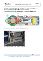
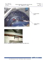
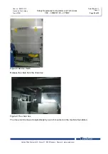
The rotor locking system is located at the upper right hand side of the main gear,
see Picture 12 Rotor locking system.
1.
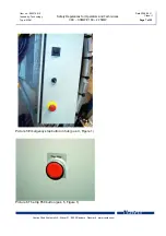
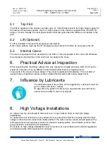
Set the turbine to PAUSE mode and select test picture 11.7 (Manual Pitch and Brake), where
the brake can be activated.
2.
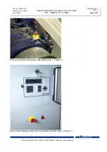
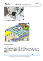
Align the locking system position holes in the hub with the locking system mandrels by
"manoeuvring" the brake (press [ * ]) until the V-notch marking (pos. 1) on the hub is aligned
with pointer on machine foundation (see pos. 2). See Picture 13.
3.
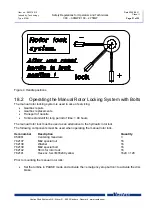
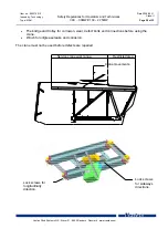
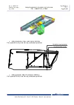
At the correct position set the handle in "+" position and pump the locking system mandrels
out. Observe at the right side during the pumping! See Figure 4.
4.
The locking takes place with the hydraulic hand pump located above the main gear on right
hand side. The locked position of the handle is 45°. When locking set the handle in ”+" position
(the handle perpendicular to the gearbox centre shaft). When unlocking set the handle in "-"
position and pump in the locking system mandrels.
5.
When the mandrels are fully out or in, set the handle in "lock" position, see Figure 4.
Verify the fully in or out position by looking at picture 11.7.B at the operator panel.

