background image

Vestfrost Solutions              3

DE

INHALT

WARNUNG  �  �  �  �  �  �  �  �  �  �  �  �  �  �  �  �  �  �  �  �  �  �  �  �  �  �  �  �  �  �  �  �  �  �  �  �  �  �  � 4

PRODUKTBESCHREIBUNG  �  �  �  �  �  �  �  �  �  �  �  �  �  �  �  �  �  �  �  �  �  �  �  �  �  �  �  �  �  � 7

Vor dem Gebrauch  �  �  �  �  �  �  �  �  �  �  �  �  �  �  �  �  �  �  �  �  �  �  �  �  �  �  �  �  � 7
Elektrische Verbindung  �  �  �  �  �  �  �  �  �  �  �  �  �  �  �  �  �  �  �  �  �  �  �  �  �  �  � 8
Verwendungszweck �  �  �  �  �  �  �  �  �  �  �  �  �  �  �  �  �  �  �  �  �  �  �  �  �  �  �  �  � 9
Klimaklasse  �  �  �  �  �  �  �  �  �  �  �  �  �  �  �  �  �  �  �  �  �  �  �  �  �  �  �  �  �  �  �  �  � 9

GERÄTEKOMPONENTE  �  �  �  �  �  �  �  �  �  �  �  �  �  �  �  �  �  �  �  �  �  �  �  �  �  �  �  �  �  �  �  10

Von vorne und Innen gesehen �  �  �  �  �  �  �  �  �  �  �  �  �  �  �  �  �  �  �  �  �  �  10
Von hinten gesehen �  �  �  �  �  �  �  �  �  �  �  �  �  �  �  �  �  �  �  �  �  �  �  �  �  �  �  �  11
Fühlerplatzierung  �  �  �  �  �  �  �  �  �  �  �  �  �  �  �  �  �  �  �  �  �  �  �  �  �  �  �  �  �  12

DISPLAYTEILE   �  �  �  �  �  �  �  �  �  �  �  �  �  �  �  �  �  �  �  �  �  �  �  �  �  �  �  �  �  �  �  �  �  �  �  �  13

INSTALLATION UND INBETRIEBNAHME  �  �  �  �  �  �  �  �  �  �  �  �  �  �  �  �  �  �  �  �  �  �  14

Lüftungsschutz   �  �  �  �  �  �  �  �  �  �  �  �  �  �  �  �  �  �  �  �  �  �  �  �  �  �  �  �  �  �  14
Batterie-Backup  �  �  �  �  �  �  �  �  �  �  �  �  �  �  �  �  �  �  �  �  �  �  �  �  �  �  �  �  �  �  15
Aufstellen und Belüftung    �  �  �  �  �  �  �  �  �  �  �  �  �  �  �  �  �  �  �  �  �  �  �  �  16
Nivellieren des Gerätes   �  �  �  �  �  �  �  �  �  �  �  �  �  �  �  �  �  �  �  �  �  �  �  �  �  17
Durchgangsloch �  �  �  �  �  �  �  �  �  �  �  �  �  �  �  �  �  �  �  �  �  �  �  �  �  �  �  �  �  �  18
Fernalarmfunktion   �  �  �  �  �  �  �  �  �  �  �  �  �  �  �  �  �  �  �  �  �  �  �  �  �  �  �  �  19

INNENEINRICHTUNG BESTÜCKUNG   �  �  �  �  �  �  �  �  �  �  �  �  �  �  �  �  �  �  �  �  �  �  �  20

STEUEREINHEIT - BETRIEB UND FUNKTION   �  �  �  �  �  �  �  �  �  �  �  �  �  �  �  �  �  �  �  21

WARTUNG  �  �  �  �  �  �  �  �  �  �  �  �  �  �  �  �  �  �  �  �  �  �  �  �  �  �  �  �  �  �  �  �  �  �  �  �  �  �  22

ALLGEMEINE INFORMATION  �  �  �  �  �  �  �  �  �  �  �  �  �  �  �  �  �  �  �  �  �  �  �  �  �  �  �  �  23

Reklamation, Ersatzteile und Service  �  �  �  �  �  �  �  �  �  �  �  �  �  �  �  �  �  �  23

ENTSORGUNG �  �  �  �  �  �  �  �  �  �  �  �  �  �  �  �  �  �  �  �  �  �  �  �  �  �  �  �  �  �  �  �  �  �  �  �  24

Summary of Contents for ULTF-37

Page 1: ...models ULTF 37 VTS 098 B IOMEDICAL SOLUTIONS FREEZERS GEFRIERGER TE CONG LATEURS USER MANUAL EN BEDIENUNGSANLEITUNG DE NOTICE D UTILISATION FR...

Page 2: ...Original instructions verified by A weighted emission sound pressure level is below 70 dB A...

Page 3: ...al view 10 Backview 11 Sensor placement 12 DISPLAY COMPONENTS 13 INSTALLATION AND START UP 14 Ventilation guards 14 Battery backup 15 Location and ventilation 16 Levelling the appliance 17 Porthole 18...

Page 4: ...he event of a leak in the refrigerant circuit WARNING Keep ventilation openings in the appliance s cabinet or in the built in structure clear of obstruction WARNING Do not use other mechanical devices...

Page 5: ...rant are used To be repaired only by trained personnel WARNING When positioning the appliance ensure the power cord is not trapped or damaged WARNING Do not locate multiple portable socket outlets or...

Page 6: ...ord fitted with a plug complies with AS NZS 3112 Frost formation on the interior evaporator wall and upper parts is a natural phenomenon Therefore the appliance should be defrosted during normal clean...

Page 7: ...visit https www vestfrostsolutions com biomedical Before operating your new appliance please read the following instructions carefully 1 Check to ensure the appliance has not been damaged during trans...

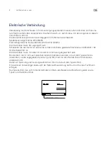
Page 8: ...be freely accessible Connect the appliance only to 220 240V 50Hz alternating current via a correctly installed earthed socket The socket must be fused with a 10A or 13A fuse If the appliance is to be...

Page 9: ...essors to operate for a prolonged time period Avoid opening the door for extended time periods since chamber temperature air will escape rapidly Also keep the inner doors closed as much as possible Wh...

Page 10: ...ock Insert the key into the keyhole and push and turn the key 180 degrees clockwise 5 Porthole Hole for external sensor and CO2 backup See chapter Installation and Start up 6 Vacuum release Ensure the...

Page 11: ...g plate 3 Porthole Hole for external sensor and CO2 backup See chapter Installation and Start up 4 Voltage free contact See chapter Remote alarm function for more information 5 Battery backup button I...

Page 12: ...2 Vestfrostsolutions com EN Sensor placement 1 TR3 Regulating probe 2 External sensor Use a 3 5mm cable tie to mount external sensor The cable tie can be found in the plastic bag 1 2 ULTF 37 VTS 098 1...

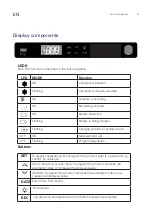
Page 13: ...g problem or battery failure C F ON Measurement unit C F Flashing Programming phase Buttons SET To display target set point in programming mode it selects a parameter og confirm an operation UP To ent...

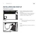
Page 14: ...The guards function is to secure an absolute minimum of ventilation if the appliance is pushed too close up against a wall Steps 1 Mount the ventilation guards in the holes on the backcover Note Some...

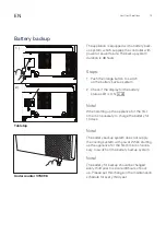
Page 15: ...N Note When starting up the appliance for the first time it is necessary to charge the battery for 10 days Note The battery backup system does not supply the cooling system with power When starting up...

Page 16: ...exposed to direct sunlight 2 A location where the unit is not exposed to rain 3 In a dry well ventilated room According to the described in Intended use 4 Away from sources of heat 5 In a location wit...

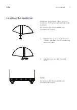
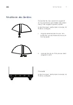
Page 17: ...of the appliance Be certain to lock the breaks for units equipped with casters 1 Some models have anti slip base for the feet Grab them from the plastic bag and mount them 2 Adjust the four feet until...

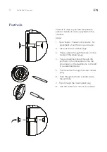
Page 18: ...two rubber plugs 3 Press a pencil through the marks on the inside of the rubber plugs 4 Put your external sensor through the porthole in the same direction as the arrow seen on the illustrations to th...

Page 19: ...ngle pole dual throw relay with maximum switch rating of 250V 3A is main tained by the build in XW737K controller unit The relay terminals are explained this way COM COMMON terminal NO NORMALLY OPEN t...

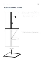
Page 20: ...ns com EN The shelves can be repositioned To remove the shelves the door must be opened at least 90 1 Remove shelf brackets from shelf rails 2 Replace shelf brackets in desired position Max 15kg INTER...

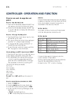
Page 21: ...Confirm by pushing SET The time and date parameters Hur hour in minutes Udy weekday dAy date on month yEA year To exit Press SET UP keys for about 10 sec How to export data and alarms to USB 1 Insert...

Page 22: ...brush 3 If frost has built up in the pipe of the vacuum release thrust with a stick to remove the frost inside X Defrost and clean the chamber to prevent ice building Quick defrosting Small amounts o...

Page 23: ...will invalidate warranty and product liability and the appliance cannot be used lawfully The approval stated on rating plate will also be invalidated Transport damage discovered by the buyer is primar...

Page 24: ...nd recycling of old products and batteries please contact your local municipality your waste disposal service or the point of sale where you purchased the items Penalties may be applicable for incorre...

Page 25: ......

Page 26: ......

Page 27: ...10 Von hinten gesehen 11 F hlerplatzierung 12 DISPLAYTEILE 13 INSTALLATION UND INBETRIEBNAHME 14 L ftungsschutz 14 Batterie Backup 15 Aufstellen und Bel ftung 16 Nivellieren des Ger tes 17 Durchgangs...

Page 28: ...o das Ger t installiert ist zu vermeiden falls eine Undichtigkeit des K hlkreislaufs entsteht WARNUNG Decken Sie die L ftungs ffnungen im Geh use des Ger tes oder am Einbaumodul nicht ab WARNUNG Verwe...

Page 29: ...fsichtigt WARNUNG Keine Produkte mit brennbaren Treibgasen z B Spraydosen und keine explosiven Stoffe lagern Explosionsgefahr WARNUNG Gefahr von Feuer oder Explosion wenn brennbares K ltemit tel ist v...

Page 30: ...en Fachmann ausgewechselt werden um Gefahr zu vermeiden Relevant f r Australien Anschlussleitung mit Stecker erf llt AS NZS 3112 Bildung von Reif auf der inneren Verdampferplatte und den obersten Teil...

Page 31: ...https www vestfrostsolutions com biomedical Vor Inbetriebnahme Ihres neuen Ger tes lesen Sie bitte die Bedienungsanleitung sorgf ltig durch 1 Stellen Sie sicher dass das Ger t w hrend des Transports...

Page 32: ...iessen Sie das Ger t nur ber eine korrekt installierte geerdete Steckdose an 220 240V 50 Hz Wechselstrom an Die Steckdose muss mit einer 10 A oder 13 A Sicherung abgesichert sein Bei Ger ten die in ni...

Page 33: ...h ht vor bergehend die Innentemperatur und f hrt dazu dass die Kompressoren ber einen l ngeren Zeitraum arbeiten Vermeiden Sie es die T r f r l ngere Zeit zu ffnen da die abgek hlte Luft schnell entwe...

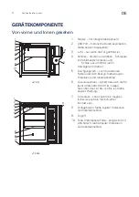
Page 34: ...angsloch Loch f r externen F hler oder CO2 Backup Siehe Kapitel Installation und Inbetriebnahme 6 Vakuumausl ser sichert dass sich die T r leicht ffnen l t WICHTIG stellen Sie sicher dass er frei von...

Page 35: ...ler oder CO2 Backup Siehe Kapitel Installation und Inbetrieb nahme 4 Spannungsfreier Kontakt Siehe Kapitel Fernalarmfunktion f r weitere Information 5 Batterie Backup Knopf Es dauert 10 Tage bis die B...

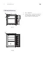
Page 36: ...12 Vestfrostsolutions com DE F hlerplatzierung 1 TR3 Regelf hler 2 Externer F hler den F hler mit dem 3 5 mm Kabelbinder befestigen Den Kabel binder finden Sie in der Plastikt te ULTF 37 VTS 098 1 1 2...

Page 37: ...eladen Blinkt Ladest rung oder Batteriefehler C F EIN Messeinheit C F Blinkt Programmierphase Tasten SET Zur Anzeige des Zielsollwerts im Programmierzustand wird ein Parameter gew hlt oder eine Aktion...

Page 38: ...die endg ltige Position gebracht wird Die Funktion dieser Schutzvorrichtungen ist eine absolutes Minimum an Bel ftung zu gew hrleisten falls das Ger t zu nahe an der Wand geschoben wird Verfahren 1 M...

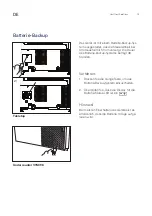
Page 39: ...des Batterie Backup Systems betr gt 48 Stunden Verfahren 1 Dr cken Sie die orange Taste um das Batterie Backup System einzuschalten 2 berpr fen Sie dass die Display f r die Batterie Status LED ist ein...

Page 40: ...er keinem direkten Son nenlicht ausgesetzt ist 2 An einem Ort an dem das Ger t keinem Regen ausgesetzt ist 3 In einem trockenen gut bel fteten Raum gem der Angaben im Kapitel Verwend ungszweck 4 Das G...

Page 41: ...gestellt werden Achten Sie darauf die Bremsen f r Ger te mit Rollen zu verriegeln 1 Einige Modelle Nehmen Sie das Anti Rutsch Teil aus der Plastikt te und es am Fu montieren 2 Justieren Sie die vier F...

Page 42: ...istopfen entfernen 3 Einen Bleistift durch die Markierungen auf der Innenseite der Gummistopfen pressen 4 Den externen F hler durch das Durch gangsloch in derselben Richtung wie der Pfeil in den Abbil...

Page 43: ...schalter mit einer maximalen Schaltleistung von 250 V 3A wird von der eingebauten XW737K Steuerein heit gewartet Die Relaisklemmen sind wie folgt erkl rt COM COMMON Gew hnliche Klemme NO NORMALLY OPEN...

Page 44: ...den k nnen neu positioniert werden Um die Einlegeb den zu entfernen muss die T r mindestens 90 ge ffnet werden 1 Die Tr ger von den Schienen entfernen 2 Die Tr ger in der gew nschten Position anbring...

Page 45: ...mit UP oder DOWN ndern Mit SET best tigen Zeit und Datumsparameter Hur Stunde in Minuten Udy Wochentag dAy Datum on Monat yEA Jahr Zum Verlassen Tasten SET UP f r ca 10 Sek dr cken Daten und Alarmexpo...

Page 46: ...uu mausl sers Reif gebildet hat mit einem Stock sto en um den Reif zu entfernen X Das Ger t abtau en und reinigen um Eisbildung zu vermeiden Schnelles Abtauen Kleine Mengen von losen Reif kann mit ein...

Page 47: ...hler und Sch den die der Lieferant nachweislich auf andere Ursachen als Fabrikations und Materialfehler zur ckf hren kann Diese Fehler oder Sch den fallen nicht unter das Reklamationsrecht Transportsc...

Page 48: ...n Sie sich bitte an Ihre rtlichen Verwaltungsbeh rden Ihren Abfallentsorgungsdienstleister oder an die Verkaufseinrichtung in der Sie die Gegen st nde gekauft haben Gem Landesvorschriften k nnen wegen...

Page 49: ......

Page 50: ......

Page 51: ...re 11 Placement des sondes 12 L MENTS DE L CRAN 13 INSTALLATION ET MISE EN MARCHE 14 Gardes de ventilation 14 Batterie de secours 15 Emplacement et ventilation 16 Mise niveau de l appareil 17 Trou de...

Page 52: ...les orifices de ventilation situ s sur la carrosserie de l appar eil ou autour de l appareil libres de toute obstruction AVERTISSEMENT Ne pas utiliser d appareils m caniques ou autres moyens pour ac c...

Page 53: ...eurs inflammables dans l appareil AVERTISSEMENT Danger risque d incendie ou d explosion si un r frig rant inflamma ble est utilis L appareil doit seulement tre r par par un personnel qualifi AVERTISSE...

Page 54: ...ustralie le c ble d alimentation quip d une fiche est conforme AS NZS 3112 La formation de givre sur les parois int rieures de l vaporateur et les parties sup rieures est un ph nom ne naturel et norma...

Page 55: ...la notice sont disponibles sur https www vestfrostsolutions com bio medical Avant d utiliser votre nouvel appareil veuillez lire attentivement les instructions suivantes 1 V rifiez que l appareil n a...

Page 56: ...ncher la fiche m le de l appareil dans une prise secteur en 220 240 V 50Hz r glementairement reli e la terre La prise doit tre prot g e par un fusible disjoncteur supportant de 10 A ou 13 A Sur les ap...

Page 57: ...ntera temporaire ment la temp rature interne et fera fonctionner les compresseurs pendant une p riode pro longu e vitez d ouvrir la porte pendant des p riodes prolonguees car l air r froidi s echapper...

Page 58: ...horloge 5 Trou de passage trou pour sonde ex terne ou sauvegarde CO2 Voir le chapitre Installation et mise en marche 6 D clencheur de vide assure que la porte s ouvre facilement IMPORTANT assurez vous...

Page 59: ...sauvegarde CO Voir le chapitre Installation et mise en marche 4 Contact sans tension Voir le chapitre Fonction d alarme dis tance pour plus d informations 5 Bouton de batterie de secours il faudra 10...

Page 60: ...utions com FR Placement des sondes 1 TR3 Sonde de r gulation 2 Sonde externe utilisez un attache c ble de 3 5 mm pour monter la sonde externe L attache c ble se trouve dans le sac en plastique ULTF 37...

Page 61: ...e recharge ou faute de batterie C F ALLUM E Unit de mesure C F Clignotement tape du programme Boutons SET Pour afficher un point de r glage cible en mode programmation cela choisit un param tre ou con...

Page 62: ...est d assurer un min imum absolu de ventilation si l appareil est pouss trop pr s contre un mur Proc d 1 Montez les gardes de ventilation dans les trous l arri re de l appareil Remarque Certains mod...

Page 63: ...ie de secours est de 48 heures Proc d 1 Appuyez sur le bouton orange pour activer le syst me de batterie de secours 2 V rifiez que la lumi re LED affichante l t t de la batterie est allum e Remarque L...

Page 64: ...pos la lumi re directe du soleil 2 Dans un endroit ou l appareil n est pas expos la pluie 3 Dans une pi ce s che et bien ventil e selon les informations dans le chapitre Utilisation pr vue 4 Tenez l a...

Page 65: ...reil Assurez vous de verouiller les freins sur les appareils roulettes 1 Certains mod les Sortez la base an tid rapante du sac en plastique et montez la sur le pied 2 R glez les quatres pieds jusqu ce...

Page 66: ...travers les marques l int rieur des bouchons en caoutch ouc 3 Faites passer la sonde externe travers le trou de passage dans le m me sens que la fl che visible sur les illustrations gauche ou comme d...

Page 67: ...errupteur ON OFF Un relais SPDT unipolaire double course avec une valeur de commutation maximale de 250V 3A est maintenu par le contr lleur XW737K int gr Les bornes de relais sont expliqu es comme sui...

Page 68: ...FR Les tag res peuvent tre d plac es Pour les d placer la porte doit tre ouverte au moins 90 1 Retirez le support d tag re de la glissi re d tag re 2 Fixez le support de nouveau la hauteur d sir e max...

Page 69: ...pour modifier le param tre Confirmez en appuyant sur SET Les param tres pour l heure et la date Hur heures in minutes Udy jour semaine dAy date on mois yEA ann e Pour quitter Appuyez sur SET UP pendan...

Page 70: ...igide 3 Si du givre s est accumul dans le tuyau du d clencheur de vide poussez l aide d un b ton pour enlever le givre au dedans X D givrez et nettoyez l appareil pour viter la formation de glace D gi...

Page 71: ...u d une modification des compo sants de l appareil a t faite la garantie et la responsabilit du fournisseur cesse et l appareil ne peut pas tre utilis l gitimement L autorisation figurant sur la plaqu...

Page 72: ...illez vous renseigner aupr s de votre mairie du service municipal d en l vement des d chets ou du point de vente o vous avez achet les articles concern s Le non respect de la r glementation relative l...

Page 73: ......

Page 74: ......

Page 75: ......

Page 76: ...Drawing no 8060904 rev 01 www vestfrostsolutions com info vestfrostsolutions com Page 1 of 1 Revision date 27 11 2020...

Reviews: