background image

18              Vestfrostsolutions.com

EN

ULTF-37i

3.2

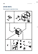
Position

Item number

Item name

0087

0-6038175

Base plate fittings, complete

0126

8-036510310

Compressor -ULTF40

0199

0-4838236

Key set 2 pcs EUROLOCKS / Kulcs szett ( 2 kulcs / szett )

0593

0-4838095

Vacuum valve

0686

6010168

Block Condenser

0727

7090465

Fan

0898

7020465

Thermostat phail

0899

7511547

Thermostat phail (defrosting)

2164

7090453

Door switch

2430

1510245

Lock push & turn / Zár

3011

8471472

Display

3104

7090466

Transformer

5002

6000959

Foot with pin/distance pieces

5017

A9101510074

Feet Ø38, M10x50 mm/Ø38 Base

5038

3021051-03

Inner door gasket

5039

3021050-03

Outer door gasket

5048

8471732

Handle

5049

A924215

Door

5050

8471314

Lock bearing

5058

3011127-03

Rubber plug for porthole

5187

6530068


Filter drier

5304

6040571

Oil separator

5346

7095665

Electronic control unit

5409

1050178-01

Hinge frontdoor

5502

A903056

Dry contact for Alarm complete

5515

A9167020004

USB key incl plug

5548

7-049954210

Nature-R - refilling with filter

5551

7010563

LED light strip

5556

6520137

Inverter 100-240V 50-60Hz

5837

A921014

Cover + wirring clamp

5860

7060046

Battery

5960

3010173-01

Ice scraper

6553

7535084

Mains lead

XXXX

1006593

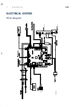
Wire diagram

Subject to changes without prior notice.

1-X04000200710590

Version

:

.

.

.

A

Date

:

.

.

.

.

.

.

.

.

.

.

.

.

.

21-02-2022

Approved by

:

.

.

.

.

sus

Spare parts list

Summary of Contents for ULTF-37i

Page 1: ...SERVICEMANUAL EN FREEZERS B IOMEDICAL SOLUTIONS models ULTF 37i...

Page 2: ......

Page 3: ...k 7 Door 8 Door gasket 11 REPLACEMENT OF PARTS IN ENGINE ROOM 12 Access to engine room 12 Inverter 13 Battery 14 COOLING SYSTEM 15 Change compressor 15 ELECTRICAL SYSTEM 16 Wire diagram 16 SPARE PARTS...

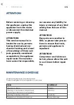
Page 4: ...EDULE TASK SCHEDULE Cleaning of interior Weekly Cleaning of compressor compartment including condenser and compressor Monthly Cleaning of sealing in the door Quarterly Replacement of battery for back...

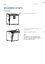
Page 5: ...OF PARTS Loosen the screws see picture Pull the top panel straight out and place it on top of the unit Unplug the wires from connector Note Be careful not to damage electric wires and not to scratch t...

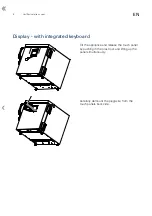
Page 6: ...com EN Display with integrated keyboard Tilt the appliance and release the touch panel by pushing in the plast lock and lifting up the panel simultanously Carefully demount the plug wire from the tou...

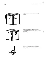
Page 7: ...y pry with screwdriver in the notch on the bottom Unscrew the bolt Remove handle Assemble the new handle as illustrated in the picture to the left Now install the new handle IMPORTANT Remember to use...

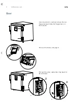
Page 8: ...tsolutions com EN Door Use screwdriver to carefully remove the two hinge plastcaps hiding the hingescrews on the doorside Remove the display see page 6 Pull out the wire cable ties may need to be remo...

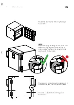
Page 9: ...tions 9 EN Support the door and remove the six hinge screws Use the handle to free the door from the cabinet when the door is free lift it away from the hinges Follow the step in chapter replacement o...

Page 10: ...mounting the hinge covers make sure that the locking rings are turned around so that the wider area with the holes is facing as shown in the illustration The new door is mounted with a distance of 9 m...

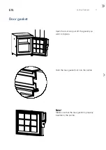
Page 11: ...frost Solutions 11 EN Door gasket Open the door and pull off the gasket you want to replace Push the new gasket foot into the profile Note Make sure that the new gasket is properly inserted in the pro...

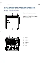
Page 12: ...N REPLACEMENT OF PARTS IN ENGINE ROOM Access to engine room Take the IEC plug out of the unit Loosen the 6 screws a few milimeters Remove the backplate 1 2 3 1 Battery 2 Controller 3 Inverter 4 Transf...

Page 13: ...ic wire on the inverter Note Ensure that the unit is unplugged and that there is no power on 2 Loosen two screws and remove inverter 3 Mount the NEW inverter with the screws you just unscrewed 4 Insta...

Page 14: ...Note Ensure that the unit is unplugged and that there is no power on 2 Cut and remove the cable ties 3 Take out the old battery and put in the NEW 4 Mount the new battery with two new cable ties 5 Ins...

Page 15: ...rtant to cut out the filter drier as heating with solder flame will release moisture inside the dry filter This will vaporize and drive moisture from filter drier back into system The quantity and typ...

Page 16: ...16 Vestfrostsolutions com EN ELECTRICAL SYSTEM Wire diagram 1006593 02...

Page 17: ...Vestfrost Solutions 17 EN Spare parts exploded view SPARE PARTS...

Page 18: ...101510074 Feet 38 M10x50 mm 38 Base 5038 3021051 03 Inner door gasket 5039 3021050 03 Outer door gasket 5048 8471732 Handle 5049 A924215 Door 5050 8471314 Lock bearing 5058 3011127 03 Rubber plug for...

Page 19: ...F 19 HYH 20 HYL 21 SLL 860 Tenth of C F 22 SLH 200 Tenth of C F 23 CCD 24 ADS 25 ADL 26 CON 27 COF 28 CPH 29 COP 30 CSP 31 TCO 32 BCO 33 PTD 34 FCE 35 MCT 36 FOP 37 FAS 500 Tenth of C F 38 FAD 39 FSD...

Page 20: ...DDT 0 Tenth of C F 49 DDP 24 Min 50 AD1 24 Time hour 51 AD2 24 Time hour 52 AD3 24 Time hour 53 CDT 100 Tenth of C F 54 FCN 30 55 FCX 100 56 EDT 100 Tenth of C F 57 FEN 35 58 FEX 100 59 HPO 0 60 HUM 2...

Page 21: ...10 Sec 6 PHD 10 Sec 7 PCN 5 Unit 8 PCW 60 Min 9 PHN 5 Unit 10 PHW 60 Min 11 CS1 0 Bit flag 12 CS2 1 Bit flag 13 CS3 0 Bit flag 14 OR1 0 Tenth of C F 15 OR2 0 Tenth of C F 16 OP1 0 Tenth of C F 17 OP2...

Page 22: ...22 Vestfrostsolutions com EN...

Page 23: ...Vestfrost Solutions 23 EN...

Page 24: ...www vestfrostsolutions com info vestfrostsolutions com Drawing no 8195131 rev 02 Revision date 19 10 2022...

Reviews: