background image

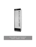
Service Manual - Low Temperatur

VTS254   VTS256   VTS 258

Summary of Contents for VTS 258

Page 1: ...Service Manual Low Temperatur VTS254 VTS256 VTS 258...

Page 2: ...acement of closing bush 21 Replacement of LED light 22 Replacement of fan 24 Replacement of Display 26 Replacement of door hinge 28 Replacement of controller 28 Recharching refrigerant VTS 254 29 Rech...

Page 3: ...odels are equipped with a battery backup system The system supplies the controller and keyboard with power at power failure This makes it possible to supervise the tempera tures in the unit during the...

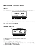
Page 4: ...ter to return from the start up view Operation main view 1 The temperature in the appliance measured by the TR3 probe 2 Time and date 3 ALARM icon Flashing by alarm On when there has been an alarm but...

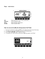
Page 5: ...r the Alarm menu How to see and modify the temperature Set Point 1 Push and immediately release the SET key the display will show the Set Point value 2 To modify the value push the SET key the Set Poi...

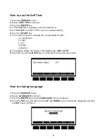
Page 6: ...ssible to change the password LANGUAGE Enter the language menu where it is possible to change language How to change parameter See the parameter list at page 26 29 1 Enter the SERVICE menu 2 Select PA...

Page 7: ...tivate the correspondent loads a Compressor b Light c Fan d Alarm e Buzzer 8 The display shows the status of the digital input ON or OFF 9 Wait 30s or push the BACK key to come back to the previous sc...

Page 8: ...u 2 Select CLOCK sub menu 3 Push the ENTER key 4 Set the day by means of the UP and DOWN keys 5 Push the SET key to confirm and pass to the setting of time 6 Use the same procedure as for the date 7 T...

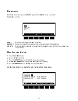
Page 9: ...ed with the appliance GRAPH Enter the graph showing the temperature logged the last 24h with a logging inter val of 15min How to enter the log 1 Enter the DATA menu 2 Select LOG sub menu 3 Push the EN...

Page 10: ...upplied by Vestfrost 3 Select ALARM or DATA the controller starts sending data to the pen drive when the export is finished the message EXPORT Copy completed is displayed The exported data will be exp...

Page 11: ...ler is switched off Alarm menu If the alarm icon is flashing on the main display an alarm is occurring If the alarm icon is displayed but not flashing on the main display an alarm is occurred and reco...

Page 12: ...ve alarms In the first line it is displayed how many alarms are happening 4 It s possible to move through the alarms by the UP and DOWN keys 5 Push the LOG button to enter the ALARM LOG This menu cont...

Page 13: ...gh temperature alarm probe TL2 Alarm output ON Other outputs unchanged LA4 Low temperature alarm probe TL2 Alarm output ON Other outputs unchanged dA Door Open Alarm Compressor and fans depend on rrd...

Page 14: ...e controller is voltage free The remote alarm should have its own power supply Some models might need changes in the parameter for the remote alarm to work 6 Locate the rating label on the back of the...

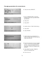
Page 15: ...to 12 with the arrow keys 15 Press SET 16 Press ENTER 17 Select Alarm relay management by pressing forward with the arrow keys and confirm with ENTER 18 The tbA parameter has to be changed for NO Thi...

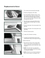
Page 16: ...r panel in the left side 6 Remove the screw in the lower panel in the right side 7 Remove the lower panel Replacement of door 8 Loosen the nut below the hinge 9 Unscrew down wards the hinge screw unti...

Page 17: ...with alcohol 6 Clean the gasket with alcohol Before mounting the new gasket the door and gasket must be cleaned an alcohol moistened cloth This is very important to ensure the gasket to stay fixed in...

Page 18: ...the gasket follow the notch to the next corner 13 Press the gasket into the notch before and after the corner Do not pull or stretch the gasket 14 Press the gasket into the notch in the entire corner...

Page 19: ...18 18 Press the gasket into the rest of the notch in the bottom 19 Cut the gasket clean off for a per fect joint...

Page 20: ...he top and the bottom of the door 4 Dismount the bushes of metal 5 Remove the handle 6 The bushes of plastic in the may not be removed 7 Mount the new handle in reverse order 8 When mounting the screw...

Page 21: ...rew in the lower panel in the left side 5 Remove the screw in the lower panel in the right side 6 Remove the lower panel 7 Remove the bolt that goes through the wheel 8 Remove the 3 nuts that fixates...

Page 22: ...ove the screw in the lower panel in the left side 5 Remove the screw in the lower panel in the right side 6 Remove the lower panel 7 Remove the nut below the hinge at the closing bush 8 Remove the bus...

Page 23: ...s to be turned off 2 Open the door 3 Unscrew the locking pawl 4 Unscrew the to screws securing the top panel 5 Open the panel 6 Unscrew the 4 screws fixing the plate with the electrical parts Replacem...

Page 24: ...ke the plate with electrical parts out of the cabinet 9 Drill out the rivets that fixates the LED light 10 Mount the new LED light with three 4 2mm thread making screws 11 Mount the plate with electri...

Page 25: ...cover 2 Dismount the compressor 3 The compressor is gently moved out of the compartment To spare the tubing please place it in the same height as it was using a wooden brick or similar 4 NOTE Be caref...

Page 26: ...25 5 Dismount the cover of the electrical box 6 Pull out the plug for the fan 7 Dismount the fan 8 Mount the new fan in reverse order...

Page 27: ...4 Unscrew the to screws securing the top panel 5 Open the panel 6 Dismount the plug on the print board of the display 7 Unscrew the 4 screws in the corners of the print board 8 Take off the print boa...

Page 28: ...lastic part is placed on the print board 12 Put in the screws in each corner 13 Make sure that all 6 buttons are placed correctly on the front of the toppanel by pushing each button click 14 Close the...

Page 29: ...ler 5 Put the new controller in place and push down to fasten the controller click 1 Dismount the door according to Replace ment of door page 13 2 Note the distance between the hinge and the front of...

Page 30: ...the compressor and let it run for 10 minutes 9 Check that the bottle especially the valve on the bottle has ambient temperature If the temperature is too cold after 10 minutes then stop the compressor...

Page 31: ...the compressor and let it run for 10 minutes 9 Check that the bottle especially the valve on the bottle has ambient temperature If the temperature is too cold after 10 minutes then stop the compresso...

Page 32: ...the compressor and let it run for 10 minutes 9 Check that the bottle especially the valve on the bottle has ambient temperature If the temperature is too cold after 10 minutes then stop the compresso...

Page 33: ...term 1 2 2 Pr2 12 12 C Probe inputs P2P Evaporator probe presence term 2 3 NO Pr2 Probe inputs oE Evaporator probe calibration 0 Pr2 12 12 C Probe inputs P3P Third probe presence term 4 5 NO Pr2 Probe...

Page 34: ...hour Temperature alarms for logging probe P4 A4U High temperature alarm for P4 75 Pr2 100 150 C Temperature alarms for logging probe P4 A4L Low temperature alarm for P4 100 Pr2 100 75 C Temperature al...

Page 35: ...tion term 1 2 2 Pr2 12 12 C Probe inputs P2P Evaporator probe presence term 2 3 NO Pr2 Probe inputs oE Evaporator probe calibration 0 Pr2 12 12 C Probe inputs P3P Third probe presence term 4 5 NO Pr2...

Page 36: ...art up 0 30 Pr2 hour Temperature alarms for logging Probe P4 A4U High temperature alarm for P4 75 Pr2 100 150 C Temperature alarms for logging Probe P4 A4L Low temperature alarm for P4 100 Pr2 100 75...

Page 37: ...probe calibration term 1 2 1 Pr2 12 12 C Probe inputs P2P Evaporator probe presence term 2 3 NO Pr2 Probe inputs oE Evaporator probe calibration 0 Pr2 12 12 C Probe inputs P3P Third probe presence te...

Page 38: ...at start up 0 30 Pr2 hour Temperature alarms for logging probe P4 A4U High temperature alarm for P4 75 Pr2 100 150 C Temperature alarms for logging probe P4 A4L Low temperature alarm for P4 100 Pr2 10...

Page 39: ...38 Plate with electrical parts A B C D E F G A Battery B Controller C Transformer D Wire to the display E Wire for battery and switch F Magnetic door contact G Wire for plug main supply...

Page 40: ...39 8195007 rev 05 Electrical diagram...

Reviews: