Rev. 6/16/2020
BOL-G MANUAL
Copyright 2020 Vestil Manufacturing Corp. Page 4 of 5
RECORD OF SATISFACTORY CONDITION (the “RECORD)
After installing the bollard, make a record of its appearance. Describe in writing the condition of the
bollard, anchoring hardware and the anchoring surface around the bollard, operating mechanisms (if
applicable), as well as the location of each label, tag, decal, etc. Take photographs of all frame
elements (mounting plate, bollard body, cap). Add the photos to the record.
These documents and
photos are a record of the unit in satisfactory condition
.
INSPECTIONS AND MAINTENANCE
When conducting the following inspections, compare your observations to the
determine if a component is in satisfactory condition. Do not use the product unless every component
is in satisfactory condition. Cosmetic changes, like damaged paint/powder coat do not constitute
changes from satisfactory condition. However, touchup paint should be applied to all affected areas as
soon as damage occurs. Contact
to order replacement parts. Contact
information appears on the cover page of this instruction manual.
At least once per month:
1. Check the surface of the product for dirt or other matter. Clean the surfaces.
2. Examine anchoring hardware. Replace damaged, worn, or corroded hardware. Confirm that the
bollard is solidly anchored to the (concrete) ground surface. Replace all anchoring hardware that is
not solidly attached to the ground. If the bollard wobbles, tighten loose anchor bolts. The bollard
should not wobble. Install the bollard in another location if wobble cannot be eliminated in the
present location.
3. Examine frame elements for excessive wear, breakages, corrosion/rusting, damage, and metal
fatigue.
4. Check all labeling. Replace labels that are damaged or not easily readable. See
5. Examine the whole structure for severe rusting/metal erosion, rot, thinned regions. If rusting is
purely superficial, remove the rust/corrosion with a steel bristle brush or steel wool. Clean the
affected area and apply touchup paint. If rusting, rot, or thinning has weakened the material, contact
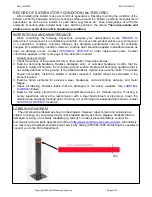
LABELING DIAGRAM
The unit should be labeled as shown in the diagram. However, label content and locations are
subject to change so your product might not be labeled exactly as shown. Replace all labels that are
damaged, missing, or not easily readable (e.g. faded). To order replacement labels, contact the
technical service and parts department online at
http://www.vestilmfg.com/parts_info.htm
. Alternatively,
you may request replacement parts and/or service by calling (260) 665-7586 and asking the operator to
connect you to the Parts Department.
252


