background image

rev. 11/1/2016 

  CB-PMPS, manual.doc 

Copyright 2016 Vestil Manufacturing Corp.                                                                                     Page 18 of 23          


VELOCITY FUSE: 

There is a brass velocity fuse with a stainless steel spring in the base of each cylinder. In the event of a hydraulic hose 

or fitting failure, the platform starts to lower at a fast rate. As soon as the descent speed exceeds the preset speed, the 
Velocity Fuse will shut off the oil flow and the platform will remain nearly stationary until pressure is reapplied. This safety 
feature reduces the possibility of accidental personal injury or damage to the pallet handler or load 

If air enters the system, the velocity fuse might activate although no failure occurs. To reset the velocity fuse, activate 

the pump by jogging the 

UP 

button. Immediately after resetting the velocity fuse, fully lower the carriage and remove the 

load from the forks. Cycle the carriage all the way to the top of the mast and back down several times to purge air from 
the system. 


AIR BLEED PROCEDURE: 

If the forks descend very slowly or fail to lower at all, air probably is trapped in the hydraulic circuit and must be bled 

from the system. The Pallet Server utilizes a bleeder screw at the top of the cylinder. To bleed air from the hydraulic 
circuit, follow these directions. 
1.) Completely unload the forks. 
2.) Loosen the bleeder screw at the top of the cylinder with approximately a 1/4 to 1/2 turn to allow trapped air to escape. 
Jog the motor to push air out of the system. 
4.) When the cylinder is free of air only clear hydraulic fluid will flow from the bleeder screw fitting. When you observe only 
oil flowing from the bleeder, retighten the bleeder screw. 


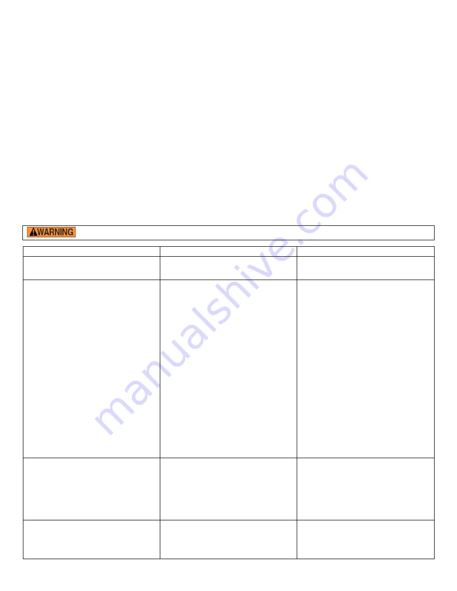
DC-POWERED HYDRAULIC SYSTEM TROUBLESHOOTING GUIDE 

 Before performing maintenance on this product, unload the forks and completely lower the carriage. 


Observation 


Possible Cause


Remedy


1. 

Unit does not raise, motor does not run


a. Low battery voltage

(Check light) 

b. All chassis connections to negative post 
of battery not made well.


a. Recharge battery 
b

Check and tighten or clean connections 

if necessary.


2. Unit does not raise but motor is running 
or humming.


c. 

Voltage at motor terminals might be too 

low to run pump at existing load. 
 
d. Fluid level in reservoir is low. 


e. Load exceeds capacity requirements

Relief valve is allowing hydraulic fluid to 
flow back into the reservoir

f. Suction filter is clogged, starving pump. 
g

Suction line may be leaking air, due to 

loose fittings. 
h. Filter/Breather cap on tank might be 
clogged. 
i. Lowering solenoid valve might be 
energized by faulty wiring or might be stuck 
open

j

Hydraulic pump might be inoperative.


c. Measure voltage at motor terminals or 
as near as possible, while pump is running 
under load. Check for loose connections. 
d

Add fluid. Refer to Owner's Manual for 

proper fluid levels

e. DO NOT CHANGE RELIEF VALVE 
SETTING. Instead, reduce the load to 
rated capacity. 
f. Remove and clean. 
g. Inspect all fittings for proper tightness. 
 
h. Remove and clean

 
i. 

Remove lowering solenoid valve. Check 

and clean. 

(Refer 

to “Lowering Solenoid 

Valves”.) 
j. Disconnect hydraulic line at power unit. 
Put pressure line in a large container and 
operate 

the 

pump. If no output

check the 

pump motor coupling which may be 
defective, and correct as necessary

If 

pump is worn

consult factory for 

replacement parts. 

3. 

Unit rises too slowly

.


k

Foreign material stuck in down solenoid 

valve, causing some fluid to flow back into 
the reservoir.  
l. Foreign material clogging suction filter, or 
breather cap, or a hose is pinched. 
m. Low motor voltage

.  

n. Unit overloaded. 
o. Inoperative pump.


k. Lower the deck

Remove the down 

solenoid valve and clean

(Refer to 

Hydraulic Section of Owners Manual). 
l

Correct as necessary. (See also

2(f), 

(h)). 
m

See 2 (b) 

n

See 2 (e) 

o. See 2 (j)


4. 

Motor labors or is excessively hot.


p. Voltage may be low. 
q. Oil starvation causing pump to bind & 
high internal heat develops. If this occurs, 
pump can be permanently damaged. 
r. Binding cylinders.


p. See 2 (b) 
q

See 2 (d), (f)

(g)

(h), (j) 


r

Align cylinders correctly. 
Summary of Contents for CB-PMPS Series

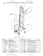
Page 1: ...om Table of Contents Hazard identification with signal words 2 Safe Use Recommendations 2 Product specifications by model 3 Diagram of Hydraulic System 3 FIG 1 CB PMPS 6 50 exploded parts diagram part...

Page 2: ...matically void the Limited Warranty see p 23 DO NOT exceed the maximum rated load see Specifications table on p 3 Label 287 on product Inspect the product before each use according to the instructions...

Page 3: ...0 cm x 91 cm 91 in 231 cm 73 in 187 cm 3 in to 50 in 7 6 cm x 127 cm 2 033 lb 923 8 kg CB PMPS 10 50 1000 lb 455 kg 4 in x 36 in 10 cm x 91 cm 91 in 231 cm 73 in 187 cm 3 in to 50 in 7 6 cm x 127 cm 2...

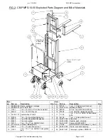
Page 4: ...zinc plated bolt 2 5 16 132 227 Caster 8 3 FWB NTP 2 17 37030 1 2in 13 Nylon insert lock nut 2 6 11365 Bolt HHCS 2 zinc plated 3 4 10x3 18 32030 8 18 x 3 4in HWH tek drill tap 2 7 11211 1 2in 13 UNC x...

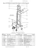
Page 5: ...SS zinc plated flat washer 8 5 16 132 173 Caster wheel PH 8 3 2 17 11105 3 8in 16 x 1in HHCS 2 zinc plated bolt 4 6 37039 3 4in 10 zinc plated Nylock nut 2 18 36106 3 8in 16 zinc plated hex nut 4 7 33...

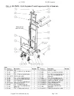
Page 6: ...16 zinc plated hex nut 4 5 37039 3 8in 10 zinc plated Nylock nut 2 17 16 001 190 FL ADJ 810 adjustable floor lock 1 6 33012 1 2in USS zinc plated flat washer 1 18 15 514 112 Weldment frame 1 7 33625 1...

Page 7: ...c plated bolt 4 5 37039 3 8in 10 zinc plated Nylock nut 2 17 36106 3 8in 16 zinc plated hex nut 4 6 33012 1 2in USS zinc plated flat washer 1 18 16 001 190 FL ADJ 810 adjustable floor lock 1 7 33625 1...

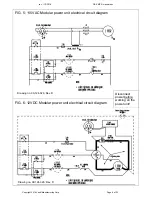
Page 8: ...Manufacturing Corp Page 8 of 23 FIG 5 115VAC Modular power unit electrical circuit diagram FIG 6 12VDC Modular power unit electrical circuit diagram Disconnect power before working on the power unit D...

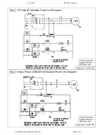
Page 9: ...ng Corp Page 9 of 23 FIG 7 3 Phase AC Modular Power Unit Diagram Disconnect power before working on the power unit Drawing no 99 124 032 FIG 7 Single Phase 208 230VAC Modular Power Unit Diagram Drawin...

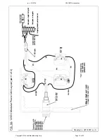
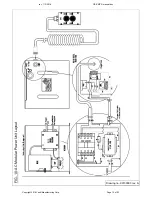
Page 10: ...rev 11 1 2016 CB PMPS manual doc Copyright 2016 Vestil Manufacturing Corp Page 10 of 23 FIG 9A 12VDC Modular Power Unit Layout part 1 of 2 Drawing no 99133001 rev A...

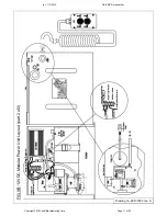
Page 11: ...rev 11 1 2016 CB PMPS manual doc Copyright 2016 Vestil Manufacturing Corp Page 11 of 23 FIG 9B 12VDC Modular Power Unit Layout part 2 of 2 Drawing no 99133002 rev A...

Page 12: ...rev 11 1 2016 CB PMPS manual doc Copyright 2016 Vestil Manufacturing Corp Page 12 of 23 FIG 10 AC Modular Power Unit Layout Drawing no 99133003 rev A...

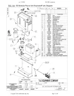
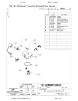
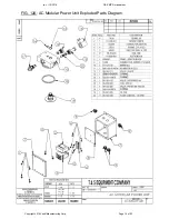
Page 13: ...rev 11 1 2016 CB PMPS manual doc Copyright 2016 Vestil Manufacturing Corp Page 13 of 23 FIG 11A DC Modular Power Unit Exploded Parts Diagram...

Page 14: ...rev 11 1 2016 CB PMPS manual doc Copyright 2016 Vestil Manufacturing Corp Page 14 of 23 FIG 11B DC Modular Power Unit Exploded Parts Diagram...

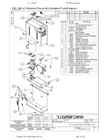
Page 15: ...rev 11 1 2016 CB PMPS manual doc Copyright 2016 Vestil Manufacturing Corp Page 15 of 23 FIG 12A AC Modular Power Unit Exploded Parts Diagram...

Page 16: ...rev 11 1 2016 CB PMPS manual doc Copyright 2016 Vestil Manufacturing Corp Page 16 of 23 FIG 12B AC Modular Power Unit Exploded Parts Diagram...

Page 17: ...To raise the forks press the UP button on the pushbutton controller This starts the electric motor which turns the hydraulic pump and oil from the reservoir then flows through the suction filter and...

Page 18: ...y voltage Check light b All chassis connections to negative post of battery not made well a Recharge battery b Check and tighten or clean connections if necessary 2 Unit does not raise but motor is ru...

Page 19: ...owly aa Lowering solenoid valve may be incorrectly wired or is stuck open bb Check valve may be stuck open cc Check for leaking hoses fittings pipes dd Cylinder packings may be worn or damaged aa See...

Page 20: ...harger to a damaged extension cord Every DC powered CB PMPS is equipped with an onboard battery charger having a flanged electrical inlet The charger is current limited and will not exceed its rated o...

Page 21: ...damaged hydraulic hoses electrical wires and cords Repair as necessary 5 Carriage rollers see diagrams on p 4 7 check rollers and retaining hardware for normal condition 6 Forks carriage and mast cyc...

Page 22: ...imited Warranty and might make the pallet handler unsafe to use Step 5 Make a dated record of the repairs adjustments and or replacements Label Placement Diagram Each unit should be labeled at all tim...

Page 23: ...y in Angola IN The warranty covers defects in the following original dynamic components motors hydraulic pumps electronic controllers switches and cylinders It also covers defects in original parts th...

Reviews:

Related manuals for CB-PMPS Series